Magnetic key switch

A magnetic and key technology, applied in electrical switches, electrical components, circuits, etc., can solve the problems of inability to adjust the pressing force, no pressing paragraph feel, no critical mutation effect, etc.

Pending Publication Date: 2021-05-18
GUANGDONG RUIXUN ELECTRONIC TECH CO LTD
View PDF0 Cites 0 Cited by
  • Summary
  • Abstract
  • Description
  • Claims
  • Application Information

AI Technical Summary

Problems solved by technology

[0003] However, the way of using magnetic force in the prior art basically adopts the direction of magnetic attraction or magnetic repulsion (usually refers to the direction of the central axis of the magnetic poles of the two magnets) and the moving direction of the movable part (usually refers to the pressing force received by the switch button). direction) is in the same direction, the force provided by this arrangement of magnetic blocks is linear and does not have a critical mutation effect. If there is no other structural part that can provide the feel, the switch button does not have any feeling of pressing the paragraph (pressing Paragraph feel refers to the feel brought by the sudden change of finger force feedback from the switch when the user presses the button switch)
[0004] In addition, in the prior art, the magnetic block is basically fixedly installed on the key base and the key shaft. When the user needs a key switch with knocking sound, it is necessary to set up additional structural parts that can provide knocking sound.
Moreover, because the fixed installation method makes the magnetic attraction or magnetic repulsion between the magnetic blocks basically constant, there is a disadvantage that the pressing force cannot be adjusted

Method used


Image

  • Magnetic key switch
  • Magnetic key switch
  • Magnetic key switch

Examples


Embodiment 1

[0032] Embodiment one: if figure 1 As shown, the movable part 1 is a key shaft, the fixed part 2 is a key seat, and the key shaft is embedded in the key seat and can move up and down relative to the key seat; the first magnetic block is installed on the key shaft, The second magnetic block is installed on the key base, and the second magnetic block is located on the adjacent side of the first magnetic block. The normal position when the key shaft is not pressed is the maximum suction force generated by the first magnetic block and the second magnetic block. When the position is determined, the central axis of the magnetic pole of the first magnetic block and the second magnetic block is perpendicular to each other when the key shaft moves up and down.

[0033] When the key switch is used, the specific installation positions of the first magnetic block and the second magnetic block are generally fixed. Since the pressing axis of the present application is perpendicular to the ...

Embodiment 2

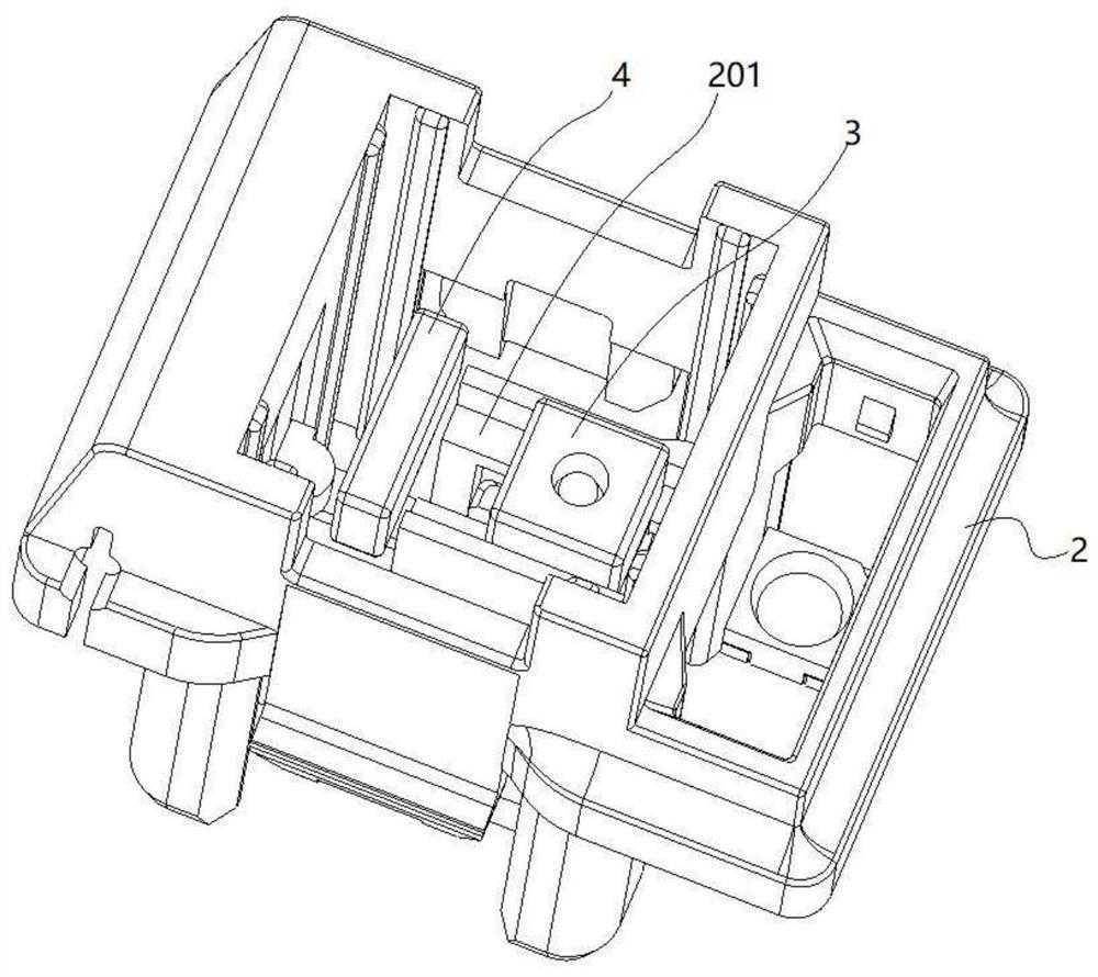
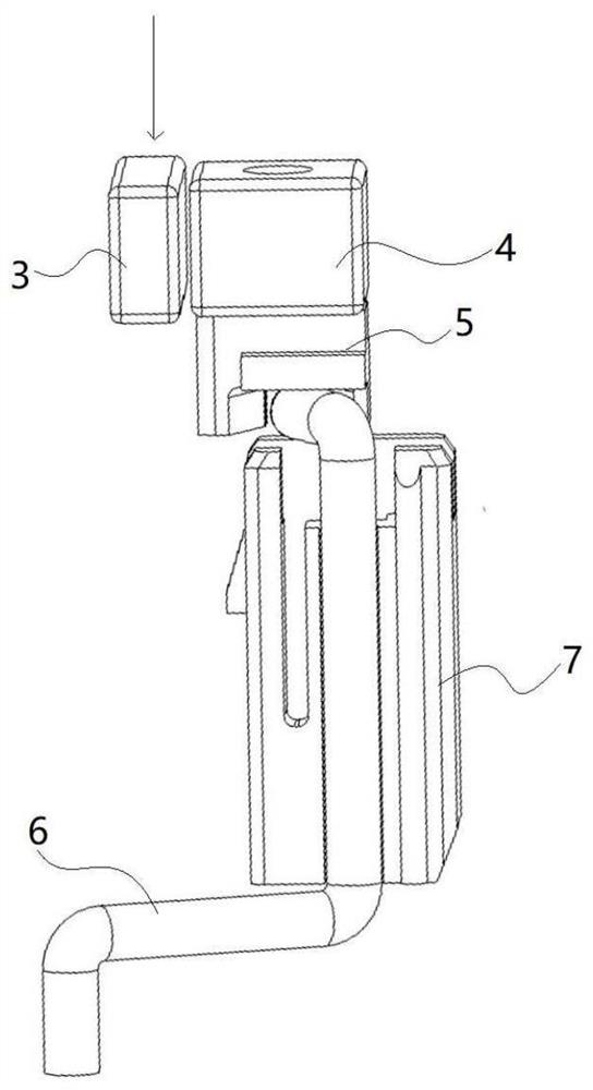
[0035] Embodiment 2 provides a kind of micro key switch: as Figure 5-8 As shown, the movable part 1 is a micro-motion pressure plate, the fixed part 2 is a micro-motion base, one end of the micro-motion pressure plate is pivotally connected to the micro-motion base, and the other end of the micro-motion pressure plate is a movable end that can be moved relatively slightly. The moving base tilts up and down; the first magnetic block 3 is installed on the movable end of the micro-movement platen, and the second magnetic block 4 is installed on the micro-moving base, and the second magnetic block is located on the adjacent side of the first magnetic block On the other hand, the normal position of the micro-movement pressure plate when it is not pressed is determined by the position when the first magnetic block and the second magnetic block generate the maximum suction force. At this time, the central axis of the magnetic pole and the movable end of the first magnetic block and t...

Embodiment 3

[0038] The third embodiment provides a scissors button switch: as Figure 9-10 As shown, the movable part 1 is a keyway, and the fixed part 2 is a key base, which also includes a scissor frame 8 pivotally connected to the key base and the key slot and a housing 9 for limiting the second magnetic block. Composed of a frame and a mother frame, a first magnetic block is provided in the keyway, and a second magnetic block is provided on the key base. When the first magnetic block and the second magnetic block are adjacent to each other, and the maximum suction force When the two magnetic blocks attract each other, the central axis of the magnetic pole and the moving direction of the pressure plate relative to the key base are perpendicular to each other; when the key slot is pressed, the first magnetic block cuts the magnetic force and the key slot moves relative to the key base; when the key slot is released, the two magnetic blocks The magnetic attraction force drives the keyway...


PUM


Abstract

The invention discloses a magnetic key switch which is characterized in that a movable part moves relative to a fixed part when being pressed, a first magnetic block is mounted on the movable part, a second magnetic block is mounted on the fixed part, and the first magnetic block and the second magnetic block attract each other when being adjacent to each other; the central axis of the attracted magnetic poles of the two magnetic blocks is perpendicular to the moving axis of the movable part relative to the fixed part when the attraction force is maximum; when the movable part is not pressed by external force, the first magnetic block and the second magnetic block attract each other and have the maximum attraction force, and when the movable part is pressed by the external force, the magnetic attraction force is cut to enable the movable part to move relative to the fixed part. According to the present invention, the two magnetic blocks are installed in the mode that the magnetic pole central axis between the two magnetic blocks is perpendicular to the action direction of the movable part, and pressing force is formed during pressing to shear the magnetic attraction force, the paragraph hand feeling of pressure sudden change of pressing fingers can be fed back, magnetic attraction force reset and sudden change hand feeling are effectively and perfectly combined, the design is ingenious, batch production is facilitated, and the market space is wide.

Description

technical field [0001] The invention relates to a key device, in particular to a magnetic key switch. Background technique [0002] Key switches are widely used in electronic products, common ones are switch shaft keys for keyboards, micro switches for mice, and so on. The user of the electronic product presses the key switch to make the movable parts inside the key switch move to trigger the relevant electronic components (such as metal electric contacts, light-emitting diodes, Hall switches, etc.) to generate switch signals. Then the key switch returns to the normal state during the time, usually adopting back-moving spring or reed etc. to be used for reset recovery. Of course, there is also a technical solution of using magnetic force as a key switch reset in the prior art, using the principle that the same poles of the magnetic blocks repel each other and the opposite poles attract each other, so that the movable parts of the key switch can return to normal after the pr...

Claims


Application Information

Patent Timeline
Patent Type & Authority Applications(China)
IPC IPC(8): H01H13/14H01H13/20
CPCH01H13/14H01H13/20
Inventor 陈爱华
Owner GUANGDONG RUIXUN ELECTRONIC TECH CO LTD
Why Eureka
Try Eureka