RFID intelligent charging cabinet

An intelligent charging cabinet and charging control technology, which is applied in different battery charging, data exchange chargers, and electricity measurement, etc., can solve the problem that the charging cabinet does not have voltage and current monitoring, the charging cabinet has a low degree of intelligence, and the placement of charging equipment Confusion and other problems, to achieve the effect of convenient and quick search, prevention of equipment damage, and convenient use

Pending Publication Date: 2021-05-18
ZHEJIANG JUNMP TECH
View PDF0 Cites 0 Cited by
  • Summary
  • Abstract
  • Description
  • Claims
  • Application Information

AI Technical Summary

Problems solved by technology

[0004] The purpose of the present invention is to provide an RFID intelligent charging cabinet to solve the problem that the traditional charging cabinet has a low degree of intelligence in the above background technology, and it is impossible to classify the models of different types of charging equipment one by one, resulting in the swing of the charging equipment. In the subsequent use process, it often takes a lot of time to find the corresponding equipment; on the other hand, the traditional charging cabinet does not have the function of monitoring the voltage and current of the power output, and with the excessive extension of the charging time, it will lead to The charging equipment is damaged; on the other hand, the staff often need to move around the charging cabinet to operate it accordingly, or observe the charging status of the charging equipment

Method used


Image

  • RFID intelligent charging cabinet
  • RFID intelligent charging cabinet
  • RFID intelligent charging cabinet

Examples


Embodiment 1

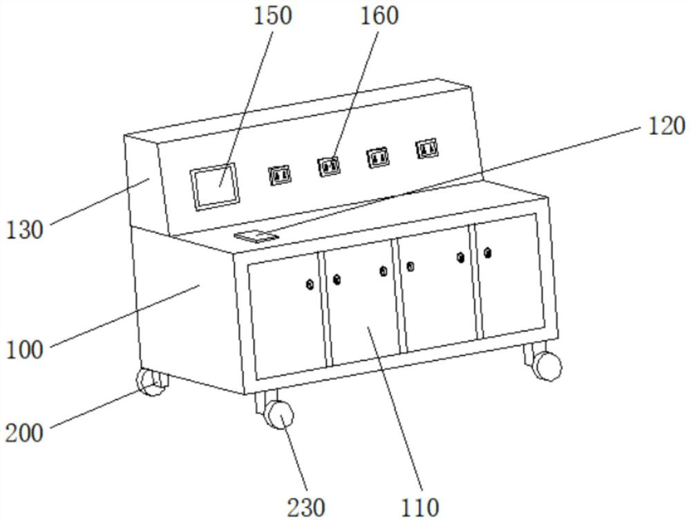
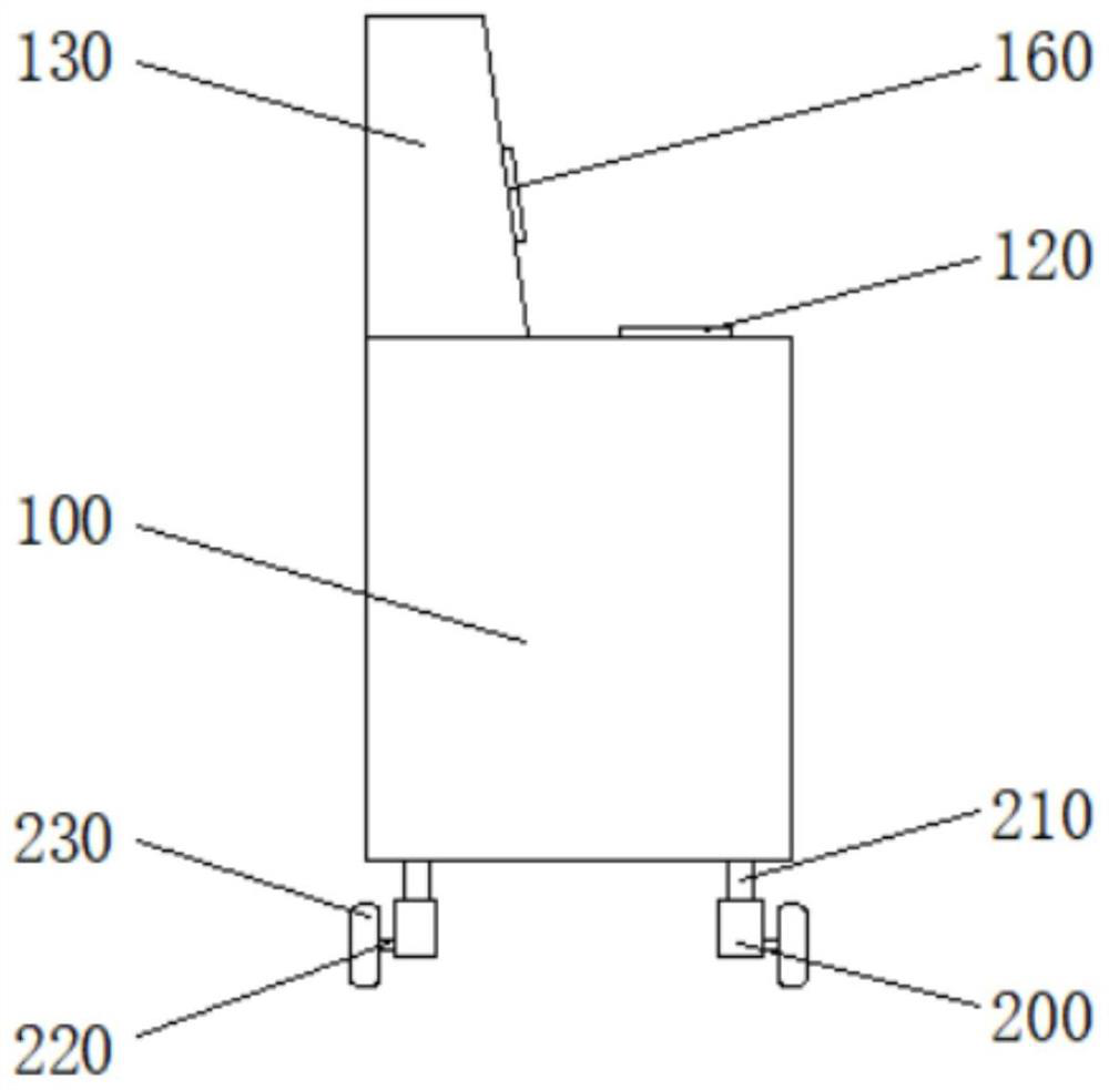
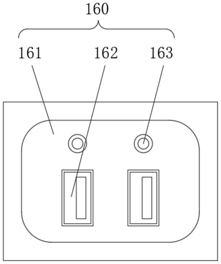
[0025]SeeFigure 1-2 withFigure 4-5 The present invention provides a technical solution: An RFID intelligent charging cabinet, comprising a stage 100, a base 200, and central processor 300 of UPS 400, 200 at the bottom corners of the base table 100, the central processor 300 located in the working The upper portion of the end of the stage 100, the output terminal of the UPS power supply 400 is electrically connected to the input of the central processor 300, and there are four storage box 110 in the front side wall of the table 100, and four storage box 110 from left. Aligned to the right, the top left side of the table 100 is inlaid with RFID antenna plate 120, and the top rear side of the table 100 is integrated with cabinet 130, and the front side wall of the cabinet 130 is inlaid with the display touch screen 150, and display The output terminal of the touch screen 150 is connected to the input of the central processor 300, and four charge mechanisms 160 are inlaid in the front s...

Embodiment 2

[0028]SeeFigure 1-5 The present invention provides a technical solution: An RFID intelligent charging cabinet, comprising a stage 100, a base 200, and central processor 300 of UPS 400, 200 at the bottom corners of the base table 100, the central processor 300 located in the working The upper portion of the end of the stage 100, the output terminal of the UPS power supply 400 is electrically connected to the input of the central processor 300, and there are four storage box 110 in the front side wall of the table 100, and four storage box 110 from left. Aligned to the right, the top left side of the table 100 is inlaid with RFID antenna plate 120, and the top rear side of the table 100 is integrated with cabinet 130, and the front side wall of the cabinet 130 is inlaid with the display touch screen 150, and display an output terminal electrically connected to the touch screen 150 at the input of the bidirectional central processor 300, the right front side wall 130 of the cabinet has...

Embodiment 3

[0031]SeeFigure 1-2 withFigure 4-6The present invention provides a technical solution: An RFID intelligent charging cabinet, comprising a stage 100, a base 200, and central processor 300 of UPS 400, 200 at the bottom corners of the base table 100, the central processor 300 located in the working The upper portion of the end of the stage 100, the output terminal of the UPS power supply 400 is electrically connected to the input of the central processor 300, and there are four storage box 110 in the front side wall of the table 100, and four storage box 110 from left. Aligned to the right, the top left side of the table 100 is inlaid with RFID antenna plate 120, and the top rear side of the table 100 is integrated with cabinet 130, and the front side wall of the cabinet 130 is inlaid with the display touch screen 150, and display an output terminal electrically connected to the touch screen 150 at the input of the bidirectional central processor 300, the right front side wall 130 of t...


PUM


Abstract

The invention discloses an RFID intelligent charging cabinet in the technical field of charging equipment. The RFID intelligent charging cabinet comprises a workbench, bases, a central processing unit and a UPS power supply. The bases are located at four corners of the bottom of the workbench, the central processing unit is located at the top of an inner cavity of the workbench, the output end of the UPS power supply is electrically connected to the input end of the central processing unit. Four storage boxes are arranged on the front side wall of the workbench. The RFID intelligent charging cabinet is reasonable in structural design, the RFID technology is combined with a traditional charging cabinet, the charging position information of charging equipment is marked, workers can conveniently and rapidly search the charging equipment. Voltage and current in the charging circuit are detected in real time, equipment damage caused by circuit instability is prevented, the use safety of the charging cabinet is improved, meanwhile, the problem that in the prior art, workers can only operate and observe the charging cabinet in a short distance is solved, and the purposes of remote monitoring and management of the device are achieved.

Description

Technical field[0001]The present invention relates to the technical field of charging equipment, in particular a RFID smart charging cabinet.Background technique[0002]With the rapid development of my country's new energy technology, the number of electric equipment in related companies has increased, in order to meet the normal use of electric equipment, equipped with corresponding quantities of charging cabinets to ensure charge efficiency of electric equipment.[0003]However, the traditional charging cabinet is less intelligent, and it is not possible to divide its model one by one for different kinds of charging equipment. It is often necessary to consume a lot of time in the subsequent time to find the corresponding equipment. It is very cumbersome to reduce its efficiency; on the other hand, the conventional charging cabinet does not have the function of monitoring the voltage and current of the power output, and as the charging time is over-extended, the charging equipment is d...

Claims


Application Information

Patent Timeline
Patent Type & Authority Applications(China)
IPC IPC(8): H02J7/00G06K17/00G01R31/385
CPCG06K17/0025G01R31/385H02J7/0031H02J7/0047H02J7/00034H02J7/00043H02J7/00047H02J7/0049H02J2207/30
Inventor 范京京林华辉叶东鑫郎晓峰吴伟锴刘平赵晖
Owner ZHEJIANG JUNMP TECH
Why Eureka
Try Eureka