Automatic winding equipment and winding method for motor coil

An automatic winding and coil technology, applied in electric components, manufacturing motor generators, electrical components, etc., can solve the problems of difficult alignment of enameled wires, affecting the winding efficiency of pay-off reels, and low threading efficiency, etc.

Active Publication Date: 2021-05-18
深圳市磐锋精密技术有限公司
View PDF11 Cites 8 Cited by
  • Summary
  • Abstract
  • Description
  • Claims
  • Application Information

AI Technical Summary

Problems solved by technology

[0005] However, in the prior art, after the enameled wire in the pay-off reel is drawn out, the pre-tightening force is applied by the tensioning unit, and the stator coil frame is wound by the winding unit, but the enameled wire drawn out from the pay-off reel is free to bend state, which in turn makes it difficult for the enameled wire to quickly align and pass through the lead hole and the tensioning unit, resulting in low threading efficiency and affecting the winding efficiency after the replacement of the pay-off reel

Method used


Image

  • Automatic winding equipment and winding method for motor coil
  • Automatic winding equipment and winding method for motor coil
  • Automatic winding equipment and winding method for motor coil

Examples


Embodiment approach

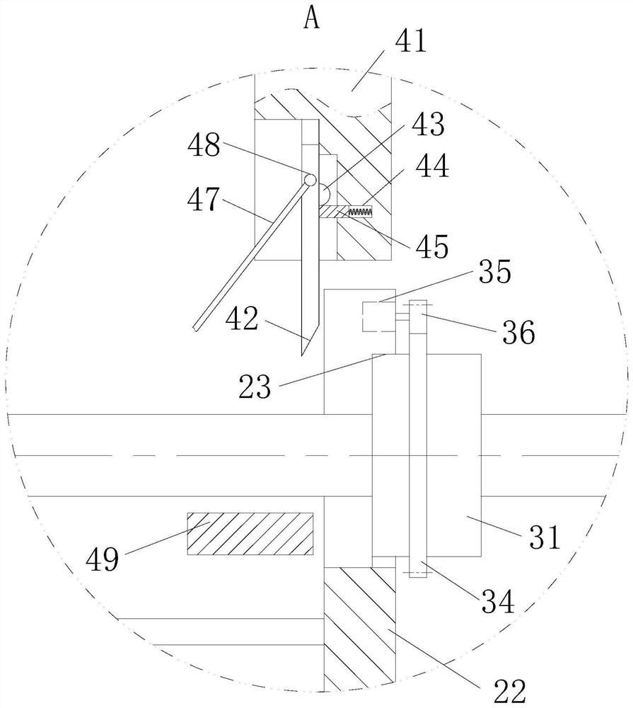
[0035]As an embodiment of the present invention, the clamping unit 3 includes a slip ring 31 and a wedge block 32; the slip ring 31 is opened away from the side of the fork 22, and the wedge block 32 is rounded. The cone hole 33 is slid in the inner circumference and the tapered hole 33; the outer circumferential insulation of the slip ring 31, the outer ring gear 34, the front and the outer gear 34, and the drive motor 35, the drive motor 35 The gear 36 of the output shaft is engaged with the outer gear 34; after the wedge block 32 is tensioned, the push rod 21 pushes the blade 22 toward the direction away from the slider 2, so that the wedge block 32 is driven in the fork 22. The lower cone hole 33 slides, and then the wedge block 32 moves in a direction in which the slide 31 is close to the center and extruded the lacquer line in the slide ring 31, thereby continuously clamping the enamel line, while driving the motor 35 drives the gear 36 to rotate, the gear 36 is driven The rin...


PUM


Abstract

The invention belongs to the technical field of winding equipment, and particularly relates to motor coil automatic winding equipment and a winding method. The automatic winding equipment comprises a rack and a pay-off reel; a shell is fixedly connected to one side of the rack through a support, an air cylinder is fixedly connected to the bottom of the shell, a clamping plate is arranged at the top of a piston rod of the air cylinder, a first sliding hole is formed in the side, close to the piston rod, of the clamping plate, and the end of the piston rod is sleeved with the first sliding hole and slidably connected with the first sliding hole in a sealed mode. A top plate is fixedly connected to the position, corresponding to the clamping plate, of the top of the shell through a support, the side, away from the pay-off reel, of the first sliding hole communicates with a sliding barrel, a push rod is slidably connected into the sliding barrel, and the end of the push rod is connected with an annular clamping unit through a shifting fork; the air cylinder pushes the clamping plate to slide upwards and clamp an enameled wire, then the clamping unit is pushed to stretch the enameled wire, the enameled wire is straightened and stretched to generate plastic deformation, the hardness of the enameled wire is increased after cold drawing, and the production efficiency of the winding equipment is further improved.

Description

Technical field[0001]The present invention belongs to the technical field of winding equipment, and is specifically a motor coil automatic winding device and a winding method.Background technique[0002]During the manufacturing process of the motor coil, the winding is generally performed by manually operating the winding machine. However, the manual operation is low, the time is long, and the work is boring and the product quality is affected by the proficiency of the workers. In particular, when the number of artificial winds is counted, the motor needs uninterrupted forward and reversal due to the winding time. The count often occurs errors, which seriously affects the production efficiency.[0003]There are also technical solutions for winding equipment, such as the application number of 2018113502574, which disclose a motor coil automatic winding device and a winding method, including a coil rack, an inward mechanism, aircraft Rack, clamping mechanism and winding mechanism; winding...

Claims


Application Information

Patent Timeline
Patent Type & Authority Applications(China)
IPC IPC(8): H02K15/04H02K15/085
CPCH02K15/0435H02K15/085
Inventor 欧文灏徐思通鲁伟赵阳李文科
Owner 深圳市磐锋精密技术有限公司
Why Eureka
Try Eureka