
Chip mounter for integrated circuit processing

A technology of integrated circuits and placement machines, which is applied in the directions of printed circuits, printed circuit manufacturing, and assembling printed circuits with electrical components, which can solve problems such as clogging of suction nozzles.

Inactive Publication Date: 2021-05-18
郑连财
View PDF0 Cites 1 Cited by
  • Summary
  • Abstract
  • Description
  • Claims
  • Application Information

AI Technical Summary

Problems solved by technology

[0002] The placement machine is also called "mounting machine" and "surface mount system". In the production line, it is configured after the dispensing machine or screen printing machine, and the surface mount components are accurately placed on the PCB by moving the placement head. A device on the pad, which is divided into two types: manual and fully automatic. The placement machine is to absorb the device stably, quickly, completely and correctly without causing any damage to the device and the basic class, and quickly place the device Mounting at the designated position has been widely used in military industry, home appliances, communications, computers and other industries. The suction nozzle on the placement machine is an important factor affecting the placement rate. When the suction nozzle on the placement head is absorbing components At the same time, due to the dust or adhesive in the external environment, especially the components packaged in paper tapes, a large amount of waste will be generated after cutting. Happening

Method used


Image

  • Chip mounter for integrated circuit processing
  • Chip mounter for integrated circuit processing
  • Chip mounter for integrated circuit processing

Examples


Embodiment 1

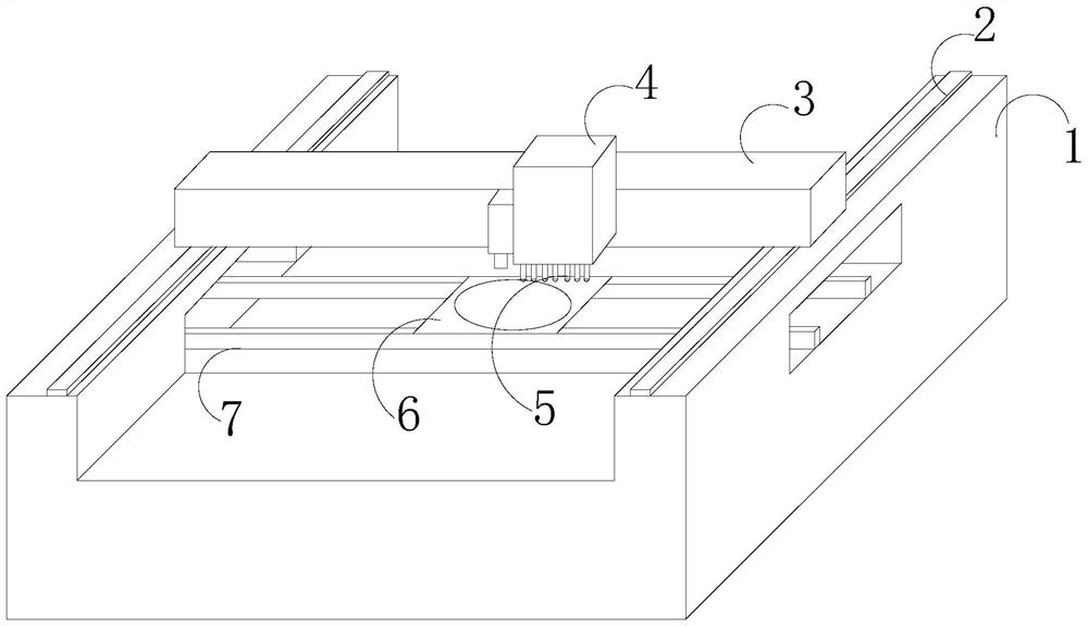
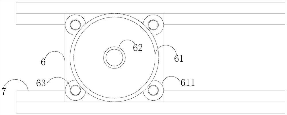
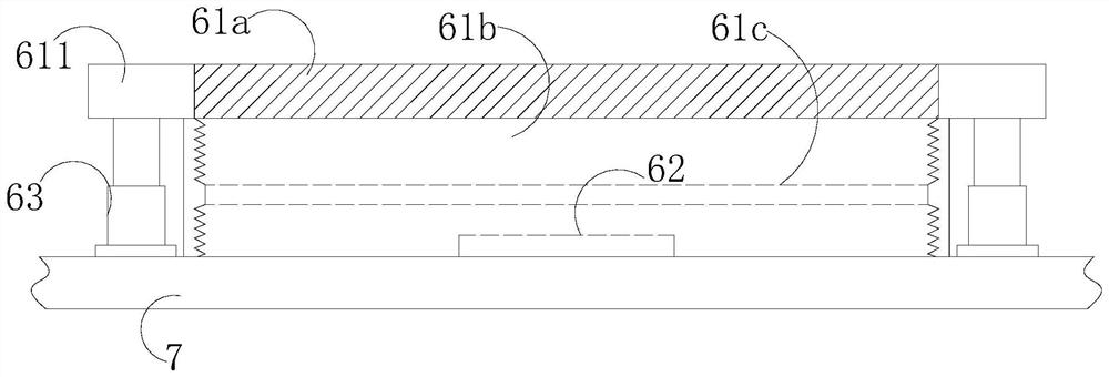
[0027] like Figure 1-Figure 6 As shown, the present invention provides a placement machine for integrated circuit processing, and its structure includes a base 1, a slide rail 2, a beam 3, a placement head 4, a suction nozzle 5, a workbench 6, and a fixing seat 7. The machine A slide rail 2 is provided on the seat 1, and the crossbeam 3 is movably fitted on the slide rail 2. The crossbeam 3 is equipped with a mounting head 4, and the bottom of the mounting head 4 is provided with a suction nozzle 5, and the suction nozzle 5 is facing the workbench 6, the workbench 6 is set on the fixed base 7, the workbench 6 includes a protection device 61, a clamping base 62, and a lifting cylinder 63, and the protection device 61 is sleeved on the clamping base 62 periphery, the lifting cylinder 63 is mechanically connected with the protective device 61, the clamping base 62 is opposite to the suction nozzle 6 up and down, the protective device 61 is a circular structure, and the four corn...


PUM


Abstract

The invention discloses a chip mounter for integrated circuit processing; the chip mounter structurally comprises a machine base, a sliding rail, a cross beam, a mounting head, a suction nozzle, a workbench and a fixed seat, the sliding rail is arranged on the machine base, the cross beam is movably matched with the sliding rail, the mounting head is mounted on the cross beam, the suction nozzle is arranged at the bottom of the mounting head and right faces the workbench, and the workbench is arranged on the fixed seat. The workbench comprises a protective device, a clamping base and lifting air cylinders, the protective device is arranged on the periphery of the clamping base in a sleeving mode, lifting air cylinders are mechanically connected with the protective device, and the clamping base is vertically opposite to the suction nozzles. The protective device is matched with the four lifting air cylinders through fixing lugs, and when the suction nozzle descends to drive the lifting air cylinders located in the four directions to ascend, a telescopic cover is taken out by the lifting air cylinders, and a pressure dust suction port formed in the telescopic cover is opened to suck scraps on the surface of the component fixed on the clamping base, so that when the component is sucked by the suction nozzle, the surface of the component is clean enough, and the suction nozzle is prevented from being blocked.

Description

technical field [0001] The invention relates to the technical field of electronic processing, in particular to a placement machine for integrated circuit processing. Background technique [0002] The placement machine is also called "mounting machine" and "surface mount system". In the production line, it is configured after the dispensing machine or screen printing machine, and the surface mount components are accurately placed on the PCB by moving the placement head. A device on the pad, which is divided into two types: manual and fully automatic. The placement machine is to absorb the device stably, quickly, completely and correctly without causing any damage to the device and the basic class, and quickly place the device Mounting at the designated position has been widely used in military industry, home appliances, communications, computers and other industries. The suction nozzle on the placement machine is an important factor affecting the placement rate. When the suct...

Claims


Application Information

Patent Timeline
Patent Type & Authority Applications(China)
IPC IPC(8): H05K3/30
CPCH05K3/303
Inventor 郑连财
Owner 郑连财
Learn More