Electronic equipment

A technology for electronic equipment and sub-faces, which is applied in branch equipment, electrical equipment shells/cabinets/drawers, electrical components, etc., and can solve problems such as difficult assembly of shells and appearance parts

Active Publication Date: 2021-05-18
HONOR DEVICE CO LTD
View PDF15 Cites 4 Cited by
  • Summary
  • Abstract
  • Description
  • Claims
  • Application Information

AI Technical Summary

Problems solved by technology

[0003] The application provides an electronic device and a middle frame, which can solve the problem that the housing and the exterior parts are difficult to assemble

Method used


Image

  • Electronic equipment
  • Electronic equipment
  • Electronic equipment

Examples


Embodiment 1

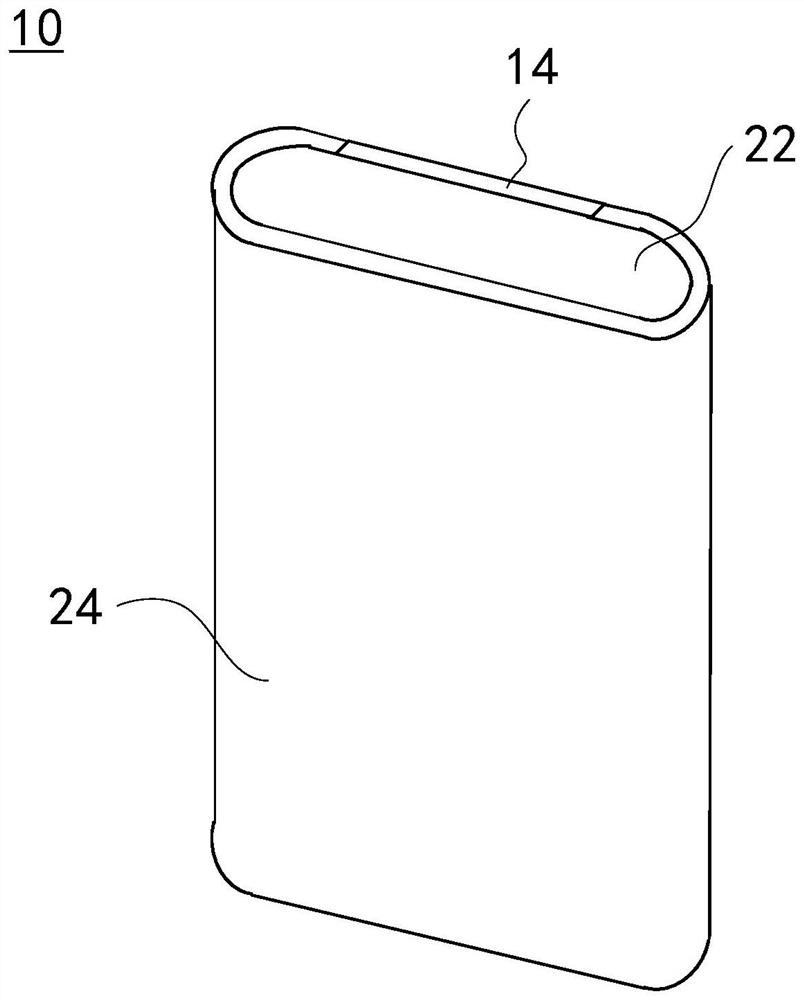
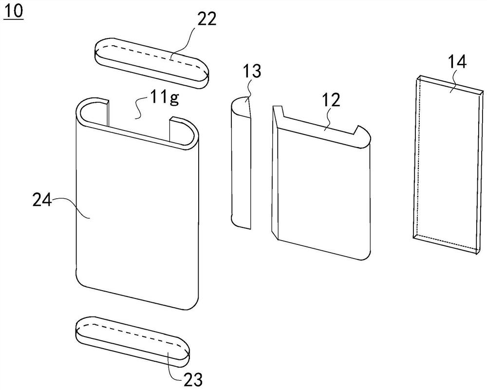
[0079] In Embodiment 1, by designing the middle frame as a split structure including the first housing 12 and the second housing 13, the first housing 12 and the second housing 13 can be respectively loaded into the housing of the curved screen module. cavity. This split-type middle frame design can meet the assembly requirements when the opening 11g between the first side part 111 and the second side part 113 in the curved screen module is relatively narrow, and the overall width of the middle frame is large, overcoming the traditional The difficulty in assembling the middle frame and the curved screen module with a large curvature facilitates the realization of a large viewing angle display design for the electronic device 10 .

[0080] Such as Figure 10 and Figure 11 As shown, in the second embodiment, the difference from the first embodiment above is that: the first engaging surface 12a is provided with a first engaging protrusion 121, and the second engaging surface 1...

Embodiment 2

[0083] In the second embodiment, the first housing 12 and the second housing 13 form a detachable connection through the engagement of the first locking protrusion 121 and the first locking groove 131, and the first housing 12 and the second housing 13 can be connected conveniently and reliably. The second casing 13 is fixedly installed in the receiving cavity of the curved screen module.

[0084] In other embodiments, the positions of the first locking protrusion 121 and the first locking groove 131 can be interchanged, that is, the first locking protrusion 121 is arranged on the second mating surface 13a of the second housing 13, and the first locking groove 131 is opened. on the first mating surface 12a of the first housing 12 . The structures of the first locking protrusion 121 and the first locking groove 131 are not limited to the above, but can be designed according to requirements, as long as the detachable connection can be realized. For example, the first protrusion...

Embodiment 6

[0093] In the sixth embodiment, through the cooperation between the first sub-surface 12a1 and the third sub-surface 13a1, and the engagement between the second engaging protrusion 123 and the second engaging groove 132, the first housing 12 and the second housing 13 can form a movable By disassembling and connecting, the first casing 12 and the second casing 13 can be conveniently and reliably fixedly installed in the storage cavity of the curved screen module.

[0094] In other embodiments, the positions of the second locking protrusion 123 and the second locking groove 132 can be interchanged, that is, the second locking protrusion 123 is arranged on the second mating surface 13a of the second housing 13, and the second locking groove 132 is opened. on the first mating surface 12a of the first housing 12 . The structure of the second locking protrusion 123 is not limited to the above, but can be designed as required, as long as the detachable connection can be realized. Fo...


PUM


Abstract

The invention provides electronic equipment. The electronic equipment comprises a first sealing cover part, a first shell and a second shell, the first sealing cover part comprises a first side part, a middle part and a second side part, the middle part is connected between the first side part and the second side part, the first side part and the second side part are opposite to each other in a spaced mode to form an opening, and the first side part, the middle part and the second side part define an accommodating cavity; the first shell and the second shell are both mounted in the accommodating cavity; in the direction from the first side part to the second side part, the first shell and the second shell are adjacent side by side; the first shell is fixedly connected with the second shell; and the first shell and the second shell are matched for supporting the first sealing cover piece. According to the scheme, the problem that the shell and the appearance part are difficult to assemble can be solved.

Description

technical field [0001] The present application relates to the field of terminal equipment, and in particular to an electronic equipment. Background technique [0002] In order to pursue a simple and consistent appearance for electronic equipment, an integrated appearance part is generally designed, and the appearance part has a main body and a side wall. A shell needs to be installed on the inner side of the appearance part to support the appearance part. However, when the housing is assembled with this type of exterior part, the housing is difficult to fit in. Contents of the invention [0003] The present application provides an electronic device and a middle frame, which can solve the problem that it is difficult to assemble the housing and the exterior parts. [0004] In a first aspect, the present application provides an electronic device, including a first cover, a first casing and a second casing; the first cover includes a first side part, a middle part and a sec...

Claims


Application Information

Patent Timeline
Patent Type & Authority Applications(China)
IPC IPC(8): H05K5/00H05K5/02H05K5/03
CPCH05K5/0217H05K5/03H04M1/0202H04M1/0249H04M1/0269H04B1/3888
Inventor 郭仁炜唐杨杰王旭阳
Owner HONOR DEVICE CO LTD
Why Eureka
Try Eureka