Integrated environment-friendly equipment control operation box
A technology for environmental protection equipment and control operation, which is applied in the direction of electrical equipment shell/cabinet/drawer, chassis/cabinet/drawer parts, electrical components, etc., and can solve the problem of narrowing the visual range of the display screen.
- Summary
- Abstract
- Description
- Claims
- Application Information
AI Technical Summary
Problems solved by technology
Method used
Image
Examples
Embodiment 1
[0026] For example figure 1 -example Figure 5 Shown:
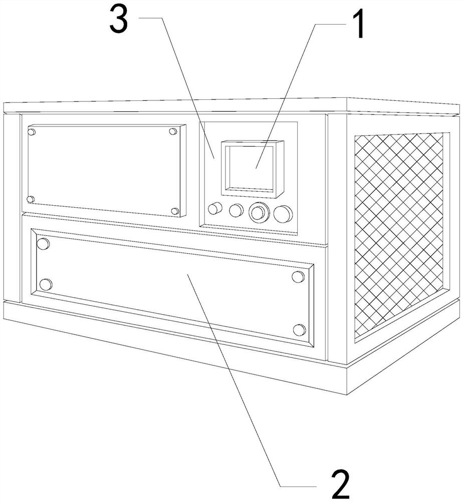
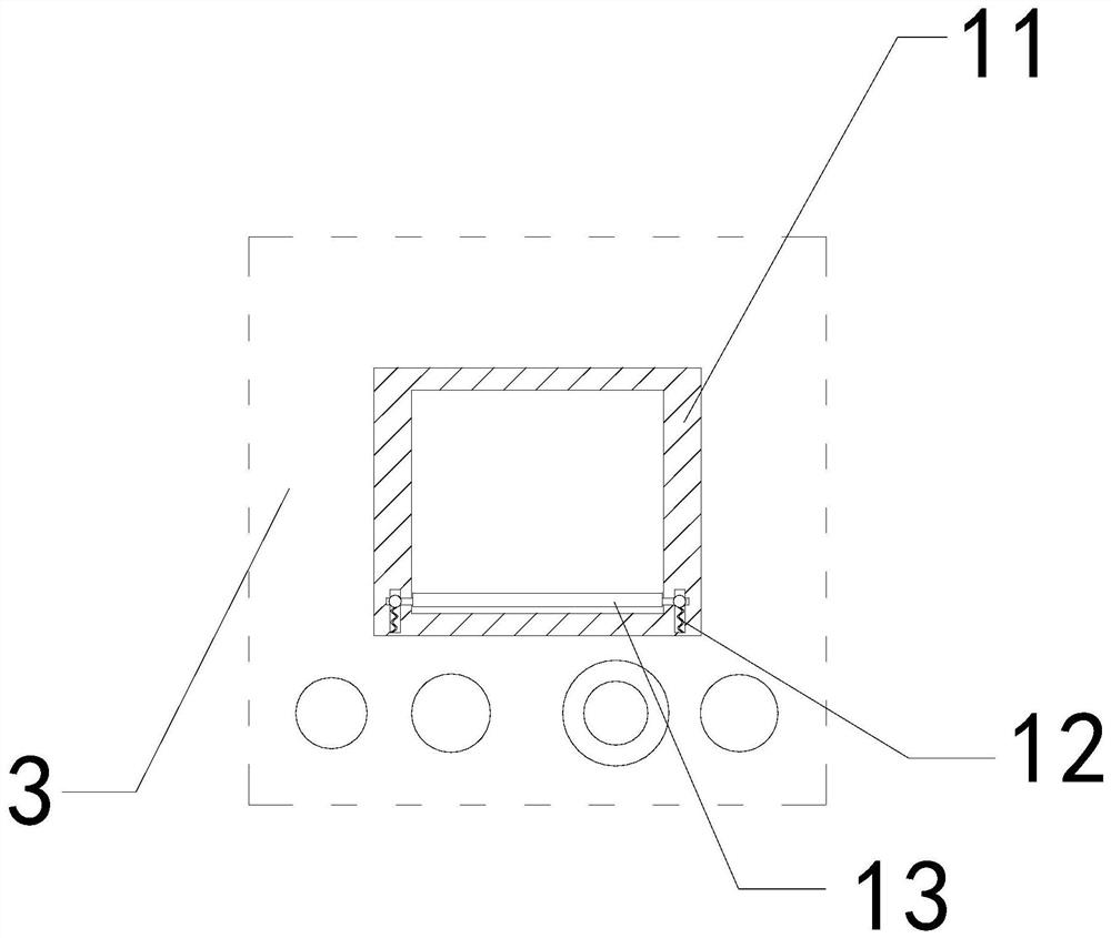
[0027] The present invention provides an integrated environmental protection equipment control operation box, the structure of which includes a display screen 1, a body 2, and a control panel 3, the control panel 3 and the body 2 are an integrated structure, and the display screen 1 is embedded in the control panel 3; the display screen 1 includes an outer frame 11, an elastic bar 12, and a force plate 13, and the elastic bar 12 is installed between the force plate 13 and the outer frame 11, and the force plate 13 and The frame 11 is movably engaged.
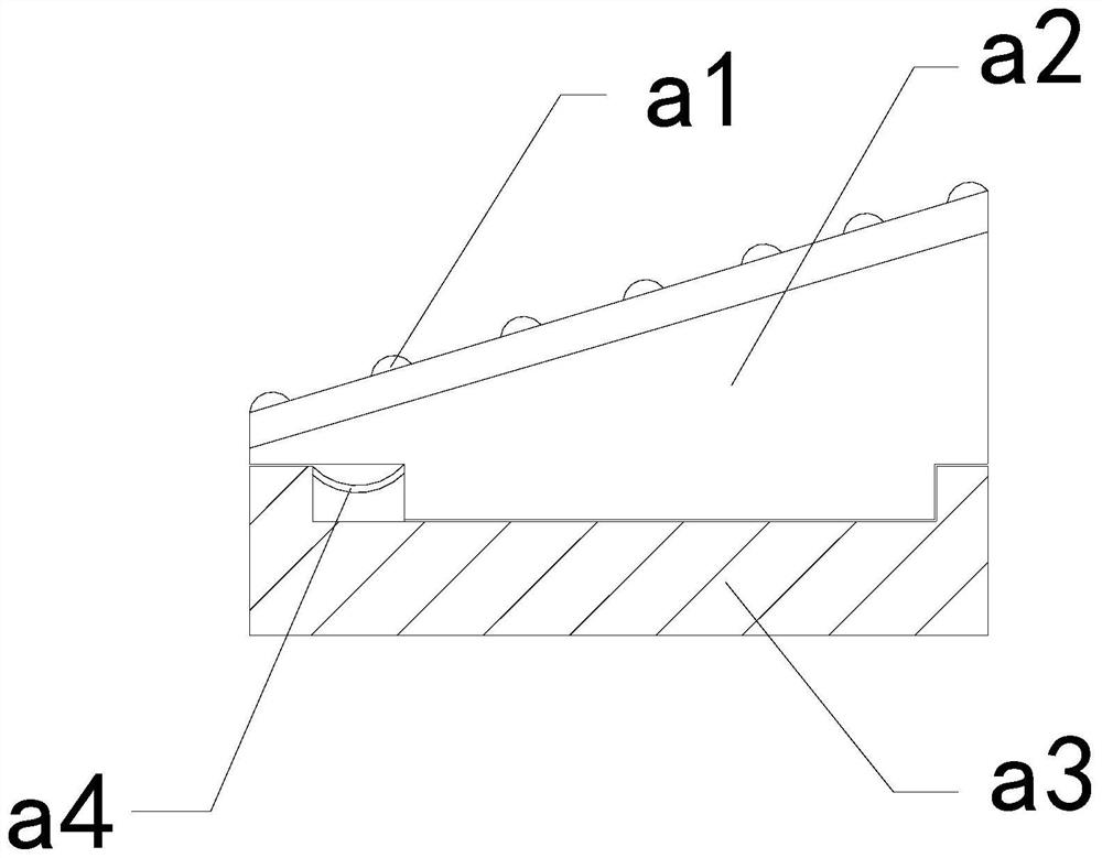
[0028] Wherein, the force bearing plate 13 includes a blocking block a1, a front sliding plate a2, a bottom plate a3, and a rebound piece a4. Together, the rebound piece a4 is installed between the base plate a3 and the front slide plate a2, and the blocking block a1 has an arc-shaped convex structure, through which the tar can push the front slide plate a2 to slide forw...
Embodiment 2
[0034] For example Figure 6 -example Figure 8 Shown:
[0035] Wherein, the cleaning roller a24 includes an outstretched rod c1, an outer ring c2, a middle solid ring c3, and an elastic strip c4. Integrated structure, the elastic bar c4 is installed between the outrigger c1 and the middle solid ring c3, there are eight outriggers c1, and they are evenly distributed in a circular shape on the outer ring c2, and rotated by the mechanism The resulting throwing force can make the outstretching rod c1 protrude outward along the outer ring c2.
[0036] Wherein, the outrigger c1 includes a frame body c11, a sliding rod c12, and a pushing block c13, the sliding rod c12 is movably engaged with the frame body c11, and the pushing block c13 is embedded in the outer position of the sliding rod c12 , through the inertial force generated by the outward extension of the mechanism, the push-off block c13 can be pushed out along the frame c11 under the cooperation of the slide rod c12,...
PUM
 Abstract
Description
Claims
Application Information
 - R&D
- Intellectual Property
- Life Sciences
- Materials
- Tech Scout
- Unparalleled Data Quality
- Higher Quality Content
- 60% Fewer Hallucinations
Browse by: Latest US Patents, China's latest patents, Technical Efficacy Thesaurus, Application Domain, Technology Topic, Popular Technical Reports.
© 2025 PatSnap. All rights reserved.Legal|Privacy policy|Modern Slavery Act Transparency Statement|Sitemap|About US| Contact US: help@patsnap.com


