Supercharge Your Innovation With Domain-Expert AI Agents!

Projection device and household appliance

一种投影装置、容置空间的技术,应用在洗印装置、清洁设备、测量装置等方向,达到提升便利性的效果

Inactive Publication Date: 2021-05-21
LITE ON OPTO TECH (CHANGZHOU) CO LTD +1
View PDF5 Cites 0 Cited by
  • Summary
  • Abstract
  • Description
  • Claims
  • Application Information

AI Technical Summary

Problems solved by technology

Opening at the front of the housing
The light source pattern module emits the imaging light source through the lens assembly and the opening in sequence

Method used


Image

  • Projection device and household appliance
  • Projection device and household appliance
  • Projection device and household appliance

Examples


no. 1 example

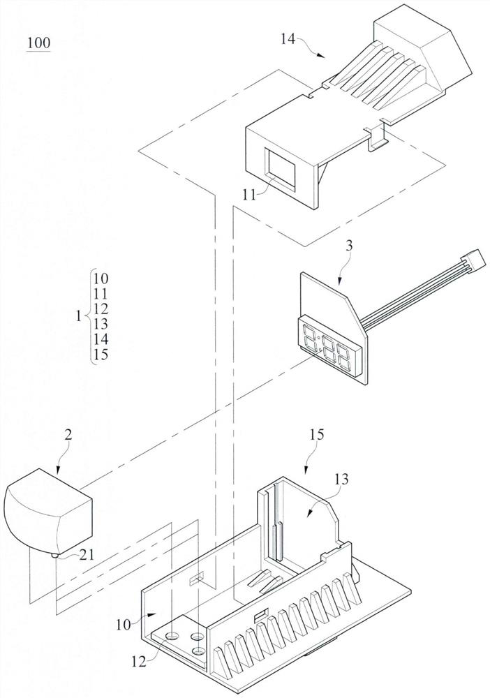
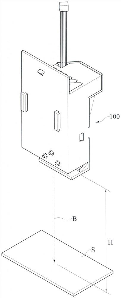
[0024] First, see figure 1 As shown, the first embodiment of the present application provides a projection device 100 , which includes: a casing 1 , a lens assembly 2 and a light source pattern module 3 . An opening 11 is defined at the front end of the housing 1 , and an accommodating space 10 is provided inside the housing 1 . The lens assembly 2 is arranged in the accommodating space 10 and fixed on the housing 1 so that the lens assembly 2 corresponds to the opening 11 . The light source pattern module 3 is also arranged in the accommodating space 10 and fixed on the housing 1 , and the light source pattern module 3 corresponds to the lens assembly 2 .

[0025] Specifically, the bottom surface of the housing 1 has a positioning hole 12 . The bottom of the lens assembly 2 is provided with a positioning post 21 corresponding to the positioning hole 12 , and the lens assembly 2 is fixed on the housing 1 by inserting the positioning post 21 into the positioning hole 12 . Th...

no. 2 example

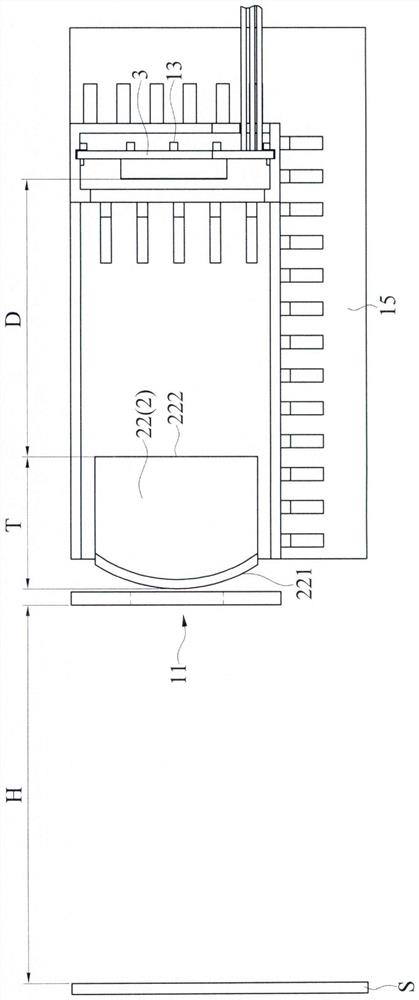
[0043] refer to Figure 11 As shown, in the second embodiment, the relative positions of the opening 11, the lens assembly 2 and the light source pattern module 3, the proportional relationship between the lens assembly 2 and the opening 11, and the operation mode of the light source pattern module 3 are all consistent with the first embodiment. One embodiment is the same, and will not be repeated here. The difference between the second embodiment and the first embodiment is that the lens assembly 2 is a biconvex lens 23 including two second convex surfaces 231 , 232 located on opposite sides. The two second convex surfaces 231 and 232 face the opening 11 and the light source pattern module 3 respectively. The thickness T of the lenticular lens 23 is 21 mm, and the curvatures of the two second convex surfaces 231 and 232 are preferably in the range of 0.025 to 0.05. In this embodiment, the curvatures of the two second convex surfaces 231 and 232 are the same and respectively...


PUM


Abstract

The invention discloses a projection device which comprises a shell, a lens assembly and a light source pattern module. An opening is formed in the front end of the shell. The lens assembly is arranged in the containing space in the shell and fixed to the shell, and the lens assembly corresponds to the opening. The light source pattern module is arranged in the containing space and fixed to the shell, and the light source pattern module corresponds to the lens assembly. The light source pattern module emits an imaging light source which sequentially passes through the lens assembly and the opening.

Description

technical field [0001] The present application relates to a projection device and household appliances, in particular to a projection device and household appliances capable of producing clear images with a single lens. Background technique [0002] Currently, household appliances, such as washing machines and dishwashers, are equipped with operation panels, and the operation panels include digital displays to display the operating conditions of the appliances. [0003] However, if the user wants to know the current operation status of the electrical equipment, such as the washing situation inside the dishwasher, he must go to the front of the dishwasher and check the digital display to confirm. This is inconvenient to a certain extent for the modern people who are busy with family affairs or work. [0004] Therefore, how to overcome the above-mentioned defects through improvement, so that users can confirm the current state of the equipment without going to the electrical ...

Claims


Application Information

Patent Timeline
Patent Type & Authority Applications(China)
IPC IPC(8): G03B21/14G03B29/00
CPCA61B5/02444A61B5/0059A61B90/08A61B2560/0462A61B2562/0233G02B27/18A47L15/4293D06F34/32G03B21/001G03B29/00G03B21/2033G03B21/145F21Y2105/16F21V5/007G01J1/0474G01J1/42G03B21/26G01J1/08H05B35/00F21K9/90F21V17/101F21Y2113/30
Inventor 李家铭
Owner LITE ON OPTO TECH (CHANGZHOU) CO LTD
Features
  • R&D
  • Intellectual Property
  • Life Sciences
  • Materials
  • Tech Scout
  • Unparalleled Data Quality
  • Higher Quality Content
  • 60% Fewer Hallucinations
Learn More