Hysteroscope and sheath body structure
A technology of hysteroscope and sheath body, which is applied in the field of uterine cavity medical treatment, which can solve problems such as short-circuit backflow, sharp cutting damage of uterine cavity, and sharp edge of the outer sheath, so as to avoid damage and accelerate discharge
- Summary
- Abstract
- Description
- Claims
- Application Information
AI Technical Summary
Problems solved by technology
Method used
Image

Examples
Embodiment 1
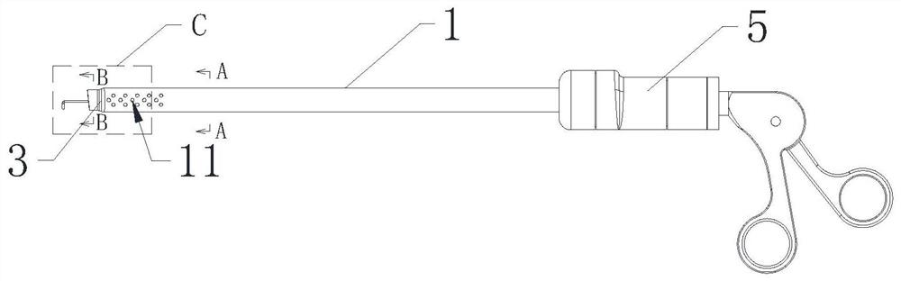
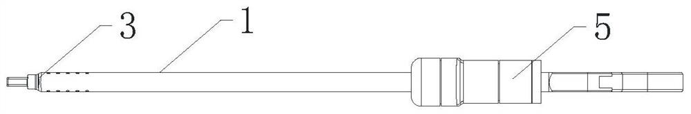
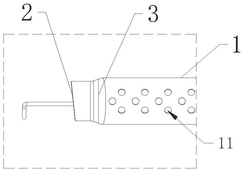
[0067] Reference manual attached Figure 1 to Figure 11 , the sheath structure of the hysteroscope provided by the present invention is set forth, and the outer sheath and the inner sheath at the far end of the sheath structure of the hysteroscope provided by the present invention are smoothly transitioned through an arc structure, which can reduce In the process of extending into the uterine cavity, the uterine cavity is damaged, and the safety performance of the hysteroscope is improved.
[0068] Specifically, the sheath structure of the hysteroscope includes an outer sheath 1 and an inner sheath 2, and the inner sheath 2 is placed in the outer sheath 1 and between the inner sheath 2 and the outer sheath 1 A backflow gap 10 is formed, and the distal end of the inner sheath 2 extends to the outside of the distal end of the outer sheath 1; wherein the cross-sectional shape of the inner sheath 2 is oval, and the distal end of the inner sheath 2 has a lens mounting Position 21;...
Embodiment 2
[0089] Reference manual attached Figure 12 to Figure 15 , the hysteroscope provided by the present invention is described, and the channel sealing mechanism of the hysteroscope provided by the present invention can better reduce the work when the working instrument 3c passes through, the working instrument 3c is replaced, and the working instrument 3c is missing. The outflow of liquid in the pipeline keeps the pressure of the liquid in the working pipeline in the range of 80-120mmHg during the use of the hysteroscope.
[0090]The hysteroscope provided by the present invention includes a hysteroscope main body 5 and the hysteroscope sheath structure described in the above preferred embodiments.
[0091] The hysteroscope also includes a channel sealing mechanism 2c and a working instrument 3c. The hysteroscope main body 5 has a working pipeline 10c; the working instrument 3c includes an instrument body and a working hand piece 32c, and the working hand piece 32c is installed o...
Embodiment 2c
[0119] Reference manual attached Figure 16The second preferred embodiment of the channel sealing mechanism of the hysteroscope provided by the present invention is described. The difference between the channel sealing mechanism of the hysteroscope of the second preferred embodiment and the above-mentioned preferred embodiment is that in In the second preferred embodiment, it further includes a sleeve assembly installed on the working instrument 3c, and the sleeve assembly can prevent the working instrument 3c from The head end is in contact with the channel sealing mechanism 2c, so that the head end of the relatively delicate working instrument 3c can be protected.
[0120] Reference manual attached Figure 16 , specifically, the hysteroscope further includes a sleeve assembly 4c, the sleeve assembly 4c is adapted to be installed on the instrument body 31c of the working instrument 3c, for The head end of the instrument body 31c is protected during installation in the worki...
PUM
 Abstract
Description
Claims
Application Information
 - R&D
- Intellectual Property
- Life Sciences
- Materials
- Tech Scout
- Unparalleled Data Quality
- Higher Quality Content
- 60% Fewer Hallucinations
Browse by: Latest US Patents, China's latest patents, Technical Efficacy Thesaurus, Application Domain, Technology Topic, Popular Technical Reports.
© 2025 PatSnap. All rights reserved.Legal|Privacy policy|Modern Slavery Act Transparency Statement|Sitemap|About US| Contact US: help@patsnap.com