Steel pipe bending equipment for construction site building

A technology for construction and steel pipes, which is applied in metal processing equipment, manufacturing tools, feeding devices, etc., and can solve problems such as manual loading and unloading.

Pending Publication Date: 2021-05-25
欧志嘉
View PDF6 Cites 0 Cited by
  • Summary
  • Abstract
  • Description
  • Claims
  • Application Information

AI Technical Summary

Problems solved by technology

[0005] In order to overcome the shortcomings of manual loading and unloading of the device, the technical problem of the present invention is to provide a steel pipe bending equipment for construction sites with automatic feeding, automatic clamping and automatic bending

Method used


Image

  • Steel pipe bending equipment for construction site building
  • Steel pipe bending equipment for construction site building
  • Steel pipe bending equipment for construction site building

Examples


Embodiment 1

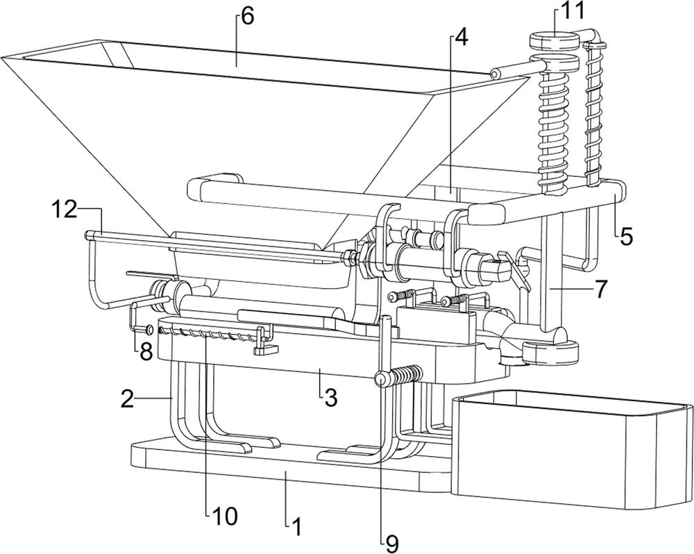
[0061] A steel pipe bending equipment for construction site construction, such as figure 1 As shown, it includes a first support plate 1, a first support frame 2, a second support plate 3, a third support frame 4, a fixed rod 5, a discharge frame 6, a bending mechanism 7, a pushing mechanism 8 and a clamping mechanism. Mechanism 9, two first support frames 2 are symmetrically arranged on the left and right sides of the first support plate 1, and the second support plates 3 are connected between the tops of the four first support frames 2, and the left and right sides of the second support plate 3 rear Both sides are provided with a third support frame 4, a fixed rod 5 is arranged between the front parts of the two third support frames 4, the left part of the fixed rod 5 is connected with a discharge frame 6, and the right side of the fixed rod 5 is provided with a bending mechanism 7 , The left side of the rear part of the discharge frame 6 is provided with a pushing mechanism...

Embodiment 2

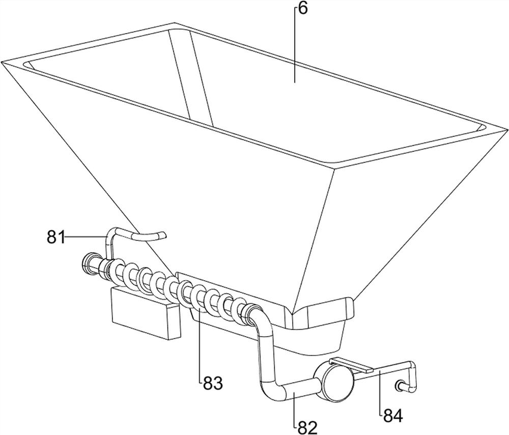
[0064] On the basis of Example 1, such as Figure 2-4 As shown, the pushing mechanism 8 includes a fourth support frame 81, a pusher 82, a second spring 83 and a first round bar 84, and the right side of the discharge frame 6 rear portion is provided with a fourth support frame 81, and the fourth The support frame 81 is slide-typely provided with a pusher 82, the front portion of the pusher 82 is provided with a first round bar 84, and a second spring 83 is connected between the pusher 82 and the fourth support frame 81, and the second spring 83 is wound on the pusher 82.

[0065] When the steel pipe in the discharge frame 6 falls on the second support plate 3, people manually push the pusher 82 to the right to drive the steel pipe to move to the right, the second spring 83 is compressed, and the first round bar 84 moves to the right Push the steel pipe into the clamping mechanism 9 to realize the effect of pushing the material, and then people let go, and the second spring 8...

Embodiment 3

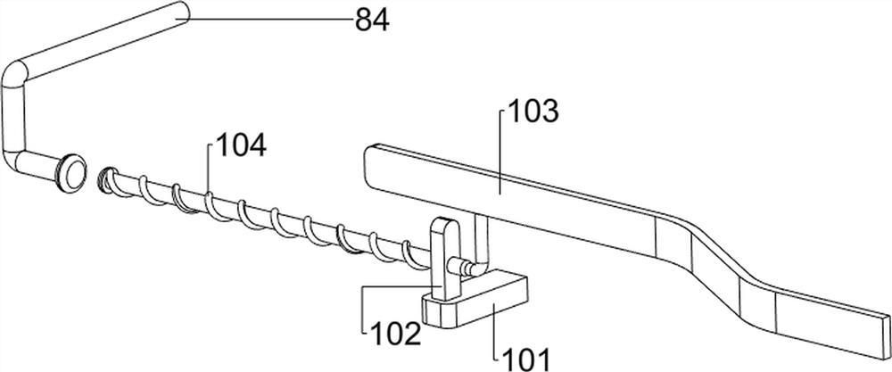
[0071] On the basis of Example 2, such as Figure 5-7 As shown, it also includes a clamping auxiliary mechanism 11. The bending auxiliary mechanism 10 includes a second fixed block 101, a third fixed block 102, a long plate 103 and a fifth spring 104. The front part of the second support plate 3 is provided with a first Two fixed blocks 101, the second fixed block 101 top front side is provided with the 3rd fixed block 102, the sliding type is provided with long plate 103 on the 3rd fixed block 102, the first round bar 84 and the second hand lever 96 are all connected with The long plate 103 cooperates, and a fifth spring 104 is connected between the long plate 103 and the third fixing block 102 , and the fifth spring 104 is wound on the long plate 103 .

[0072] When the first round bar 84 moves to the right and touches the long plate 103, the first round bar 84 drives the long plate 103 to move to the right, the fifth spring 104 is compressed, and the long plate 103 moves to...


PUM


Abstract

The invention relates to bending equipment, in particular to steel pipe bending equipment for a construction site building. The steel pipe bending equipment for the construction site building achieves automatic feeding, automatic clamping and automatic bending. The steel pipe bending equipment for the construction site building comprises a first supporting plate, first supporting frames, a second supporting plate, third supporting frames, a fixed rod, a discharging frame and a bending mechanism. The two sides of the first supporting late are each symmetrically provided with the two corresponding first supporting frames. The second supporting plate is connected among the tops of the four first supporting frames. The third supporting frames are arranged on the two sides of the second supporting plate. The fixed rod is arranged between the two third supporting frames. The discharging frame is connected to the fixed rod. The bending mechanism is arranged on the fixed rod. According to the steel pipe bending equipment, a pusher is manually pushed rightwards to drive a steel pipe to move rightwards, a second spring is compressed, a first round block rod moves rightwards, the steel pipe is pushed into a clamping mechanism, and the pushing effect is achieved.

Description

technical field [0001] The invention relates to a bending equipment, in particular to a steel pipe bending equipment for construction site. Background technique [0002] When building a construction site, it is often necessary to bend steel pipes for construction needs. The existing bending methods mostly use manual bending. Bending on the bending frame is a waste of time, and the extruded steel pipes have different arcs, which increases the difficulty of the next process and the time for steel pipe trimming. When a large number of steel pipes are bent, it can no longer keep up with the project progress, so it is necessary to design a steel pipe bending equipment. [0003] Patent application CN208116472U, publication date 20181120, discloses a steel pipe bending machine. The steel pipe is fixed to the pressure plate by a fixing device, so that the steel pipe rotates around the pressure plate with the rotation of the pressure plate to realize the bending of the steel pipe. T...

Claims


Application Information

Patent Timeline
IPC IPC(8): B21D7/06B21D7/16B21D43/00B21D43/04
CPCB21D7/06B21D7/16B21D43/003B21D43/04Y02P70/10
Inventor 欧志嘉
Owner 欧志嘉
Why Eureka
Try Eureka