Accurate positioning and stamping device for chain production

A technology of precise positioning and stamping devices, applied in the direction of metal chains, etc., can solve the problems of manual feeding and low drilling accuracy, and achieve the effect of convenient and precise positioning

Active Publication Date: 2021-04-13
杭州钱唐链条配件有限公司
View PDF19 Cites 0 Cited by
  • Summary
  • Abstract
  • Description
  • Claims
  • Application Information

AI Technical Summary

Problems solved by technology

[0004] In order to overcome the shortcomings of the existing chain punching technology, such as low punching accuracy and manual feeding, the technical problem is to provide a method that can avoid chain movement and automatically Precise positioning punching unit for chain production of conveyor chains

Method used


Image

  • Accurate positioning and stamping device for chain production
  • Accurate positioning and stamping device for chain production
  • Accurate positioning and stamping device for chain production

Examples


Embodiment 1

[0067] A precision positioning stamping device for chain production, such as figure 1 As shown, it includes a base plate 1, a workbench 2, a motor 3, a stamping mechanism 4 and a clamping and positioning mechanism 5. A workbench 2 is provided on the upper front side of the base plate 1, and a motor 3 is installed on the upper rear side of the base plate 1. The upper left side of the base plate 1 A stamping mechanism 4 is provided on the side, and the stamping mechanism 4 is connected with the output shaft on the left side of the motor 3, and a clamping and positioning mechanism 5 is provided on the left front part of the top of the workbench 2.

[0068] When people need to punch and punch chains, they can use this precise positioning punching device. First, put the chain to be punched in the clamping and positioning mechanism 5, start the motor 3, and the output shaft of the motor 3 rotates to drive the punching mechanism 4. Reciprocate up and down, the stamping mechanism 4 mo...

Embodiment 2

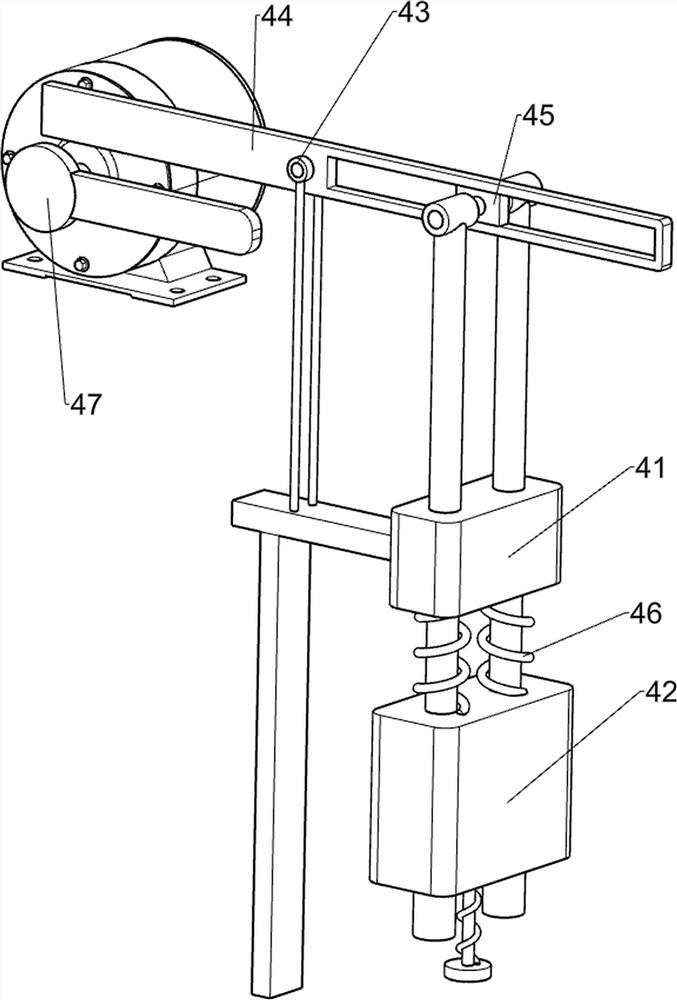
[0070] On the basis of Example 1, such as figure 2 and image 3 As shown, the stamping mechanism 4 includes a first guide sleeve 41, a stamping assembly 42, a rotating sleeve 43, a long plate 44, a first rotating moving block 45, a first tension spring 46 and a rotating plate 47. The first guide sleeve 41 is arranged, and the rear side of the first guide sleeve 41 top is provided with a rotating sleeve 43, and the rotation type on the rotating sleeve 43 is provided with a long plate 44, and the front side of the long plate 44 is provided with a first rotation moving block 45, and the first rotation A stamping assembly 42 is connected between the moving block 45 and the front side of the first guide sleeve 41, and the stamping assembly 42 is slidably connected with the first guide sleeve 41. The left and right sides of the lower part of the stamping assembly 42 are wound with a first tension spring 46, and the motor 3. A rotating plate 47 is arranged on the output shaft on the ...

Embodiment 3

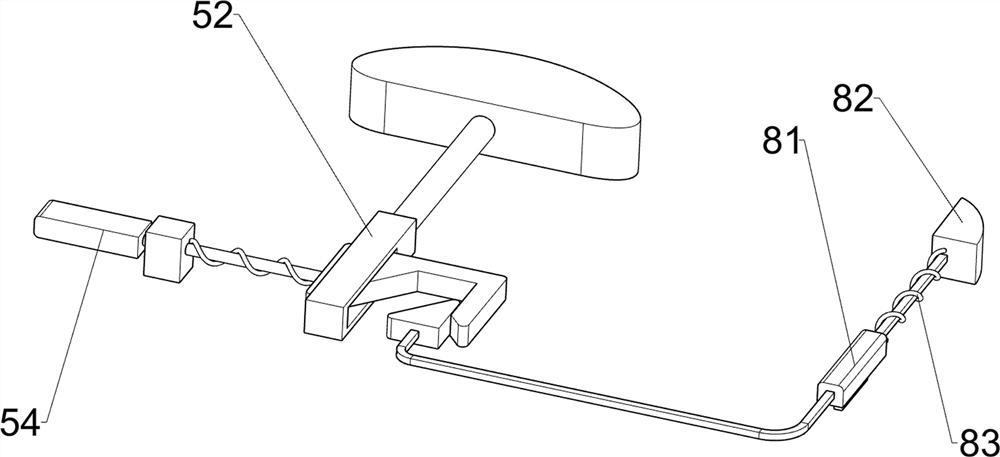
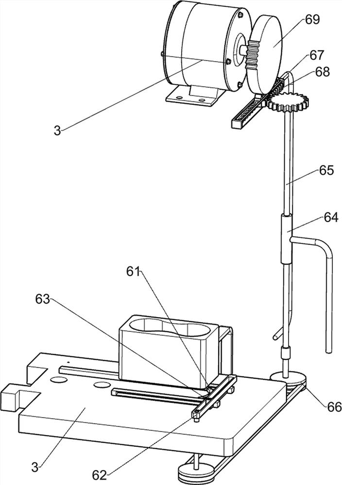
[0075] On the basis of Example 2, such as Figure 4 to Figure 7 As shown, a feeding mechanism 6 is also included, and the feeding mechanism 6 includes a push link 61, a rotating belt column plate 62, a second rotating moving block 63, a first rotating sleeve 64, a gear connecting rod 65, a transmission assembly 66, a fourth Guide assembly 67, double rack 68 and missing gear 69, the sliding type on the workbench 2 is provided with a push link 61, and the right side of the front part of the workbench 2 is rotated with a rotating belt column plate 62, which slides inside the rotating belt column plate 62 The second rotating block 63 is provided in the formula, and the second rotating block 63 is connected with the front side of the push lever 61. The bottom plate 1 is provided with a first rotary sleeve 64 on the right side of the upper rear part, and the upper part of the first rotary sleeve 64 is provided with a rotary The gear connecting rod 65, the lower part of the gear conn...


PUM


Abstract

The invention relates to an accurate positioning and stamping device, in particular to an accurate positioning stamping device for chain production. The invention provides the accurate positioning and stamping device for chain production which can prevent a chain from moving and automatically convey the chain. The accurate positioning and stamping device for chain production comprises a bottom plate, a motor, a stamping mechanism, and a clamping and positioning mechanism; a workbench is arranged on the bottom plate; the motor is mounted on the bottom plate; the stamping mechanism is arranged on the bottom plate, the stamping mechanism is connected with an output shaft on the left side of the motor; and the clamping and positioning mechanism is arranged at the top of the workbench. According to the accurate positioning and stamping device, a first rotary moving block swings up and down to drive the stamping mechanism to slide up and down, a first extension spring is adaptively stretched and reset, and the effect of stamping and punching the chain is achieved; and an elastic pushing assembly is pulled leftwards, so that a second guide sleeve slides backwards, the second guide sleeve clamps the concave position of the front wall of the chain, and therefore the chain does not deviate, and accurate positioning during punching is facilitated.

Description

technical field [0001] The invention relates to a precise positioning punching device, in particular to a precise positioning punching device for chain production. Background technique [0002] As a common part of mechanical transmission, the chain is used for transmission and traction. It is widely used in the fields of machinery, logistics and automation. The chain is mainly composed of chain plates, chain pins, shaft sleeves and other components. These components must be assembled and Assembling multiple short chains into long chains suitable for different occasions requires punching and punching of the created chains. The existing chain punching technology requires manual loading, and there is an offset phenomenon in the punching position where the chains are manually placed. , There is also the situation that the chain moves when punching holes, so that the punching accuracy is not high. [0003] In order to improve the processing technology of the existing chain punch...

Claims


Application Information

Patent Timeline
Patent Type & Authority Applications(China)
IPC IPC(8): B21L9/04B21L9/06
CPCB21L9/04B21L9/06
Inventor 莫明龙
Owner 杭州钱唐链条配件有限公司
Why Eureka
Try Eureka