Metal sheet surface milling device

A technology of metal sheet and milling device, which is applied in positioning devices, metal processing equipment, metal processing machinery parts, etc., can solve problems such as changing the position of the moving platen

Inactive Publication Date: 2021-05-25
宁波信基机械科技有限公司
View PDF17 Cites 0 Cited by
  • Summary
  • Abstract
  • Description
  • Claims
  • Application Information

AI Technical Summary

Problems solved by technology

[0004] The present invention intends to provide a metal thin plate surface milling device to solve the problem in the prior art that when the moving press plate is used to press the thin plate parts, the position of the moving press plate is easy to change with the movement of the thin plate parts

Method used


Image

  • Metal sheet surface milling device
  • Metal sheet surface milling device

Examples


Embodiment 1

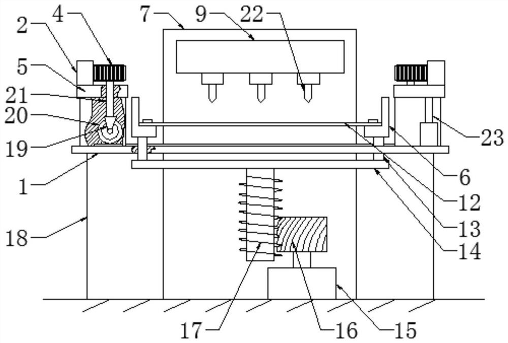
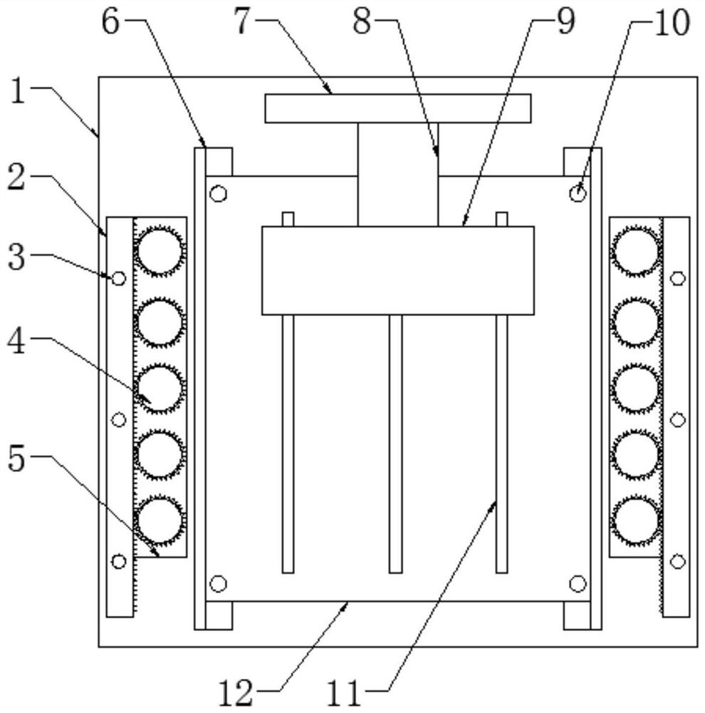
[0020] Embodiment 1 is basically as attached figure 1 with figure 2 Shown: a metal sheet surface milling device, including a frame 18, a storage table 1, a milling cutter limit mechanism, a milling mechanism fixed on the frame 18 and a fixing mechanism for pressing the metal sheet, the milling mechanism includes a connecting Milling cutter support 7 on frame 18, the cylinder 8 that is connected with milling cutter support 7, milling cutter 22 and the housing 9 that milling cutter 22 is installed, housing 9 is connected with cylinder 8 (milling mechanism is prior art, this Not much to do here), there are two fixing mechanisms, and the two fixing mechanisms are respectively located on both sides of the milling mechanism. The fixing mechanisms include a support table 5, a lifter 23, a rack 2 and five smooth cylindrical layering bars 20, The lifter 23 supports the support table 5 above the storage table 1, the rack 2 is slidably connected with the support table 5, and the rack 2...

Embodiment 2

[0022] The difference between embodiment 2 and embodiment 1 is that the lifting mechanism connected to the bottom of the support plate 14 is a hydraulic rod.

Embodiment 3

[0023] The difference between embodiment 3 and embodiment 1 is that the bead 20 is in the shape of a smooth cuboid.

[0024] Taking Embodiment 1 as an example, the specific implementation process of this scheme is as follows: the metal sheet is placed on the storage table 1, and the lifting of the support table 5 is adjusted through the elevator. Thin plate, the specific operation of this process is: the elevator descends to make the supporting platform 5 descend, the clamping plate fixes the connecting rod 21 to prevent it from sliding up and down relative to the supporting platform 5, and the bead 20 connected to the supporting platform 5 through the connecting rod 21 contacts and Stop the descent of the elevator after pressing the sheet metal.

[0025] The connecting rod 21 is connected with a gear 4, the gear 4 meshes with the rack 2, and the rack 2 is slidably connected to the support table 5, so the sliding rack 2 can make the gear 4 rotate, thereby driving the bead 20 t...


PUM


Abstract

The invention discloses a sheet metal surface milling device in the technical field of machining. The sheet metal surface milling device comprises a rack, a storage table, a milling mechanism fixed to the rack and two fixing mechanisms used for pressing a sheet metal. The number of the fixing mechanisms is two, and the two fixing mechanisms are located on the two sides of the milling mechanism correspondingly. Each fixing mechanism comprises a supporting table, a lifting machine, a rack and a pressing strip, wherein the lifting machine supports the supporting table above the storage table, the rack is in sliding connection with the supporting table, threaded holes corresponding in position are formed in the rack and the supporting table, and bolts are connected into the threaded holes. The pressing strips are located between the supporting tables and the storage table and fixedly connected with connecting rods, the connecting rods penetrate through the supporting tables in a sliding mode, each connecting rod is fixedly connected with two clamping plates making contact with the upper surface and the lower surface of the corresponding supporting table correspondingly, the tops of the connecting rods are fixedly connected with gears, and the gears are engaged with the racks. According to the scheme, the positions of the fixing mechanisms are not likely to change, and unnecessary trouble brought to workers is avoided.

Description

technical field [0001] The invention belongs to the technical field of mechanical processing, in particular to a thin metal plate surface milling device. Background technique [0002] Milling is a mechanical processing method in which a milling cutter is used as a tool to process the surface of an object. The objects of milling include planar parts and curved surface parts. Groove milling refers to the use of specific tools to mill the required grooves on the surface of the object. [0003] When the current milling machine is milling thin-plate parts, there is an upward cutting force acting on the parts, which causes the thin-plate parts to jump during the processing, which makes the milling impossible. Metal sheet is a flat part, milling on the surface of the metal sheet At the same time, due to its thin thickness and the beating of thin plate parts, it is easy to deform during the milling process, resulting in troublesome processing and more scrapped raw materials. In ord...

Claims


Application Information

Patent Timeline
Patent Type & Authority Applications(China)
IPC IPC(8): B23Q3/06B23C1/08
CPCB23Q3/06B23C1/08
Inventor 曹志恩
Owner 宁波信基机械科技有限公司
Why Eureka
Try Eureka