Automatic crimping machine terminal material belt cutting mechanism

A technology of cutting mechanism and crimping machine, which is applied in the direction of connection, metal processing, electrical components, etc., can solve the problems of uneven cutting, easy damage, and low degree of automation, and achieve the effect of reducing environmental pollution and improving stability

Inactive Publication Date: 2021-05-25
吉安市联基电子有限公司
View PDF0 Cites 3 Cited by
  • Summary
  • Abstract
  • Description
  • Claims
  • Application Information

AI Technical Summary

Problems solved by technology

[0003] The existing crimping terminal waste cutting device generally uses a cutting knife to cut the crimping terminal waste manually, and also needs to manually recycle the terminal waste. The existing crimping terminal waste cutting device lacks a terminal waste limiter. It is easy to cause uneven cutting when cutting, and the cutting knife of the crimping terminal waste cutting device is used for a long time, which is easy to be damaged and inconvenient to install and disassemble, and the existing crimping terminal waste cutting device is not highly automated.

Method used


Image

  • Automatic crimping machine terminal material belt cutting mechanism
  • Automatic crimping machine terminal material belt cutting mechanism
  • Automatic crimping machine terminal material belt cutting mechanism

Examples


Embodiment Construction

[0031] In order to make the object, technical solution and advantages of the present invention clearer, the present invention will be further described in detail below in conjunction with the accompanying drawings and embodiments. It should be understood that the specific embodiments described here are only used to explain the present invention, not to limit the present invention.

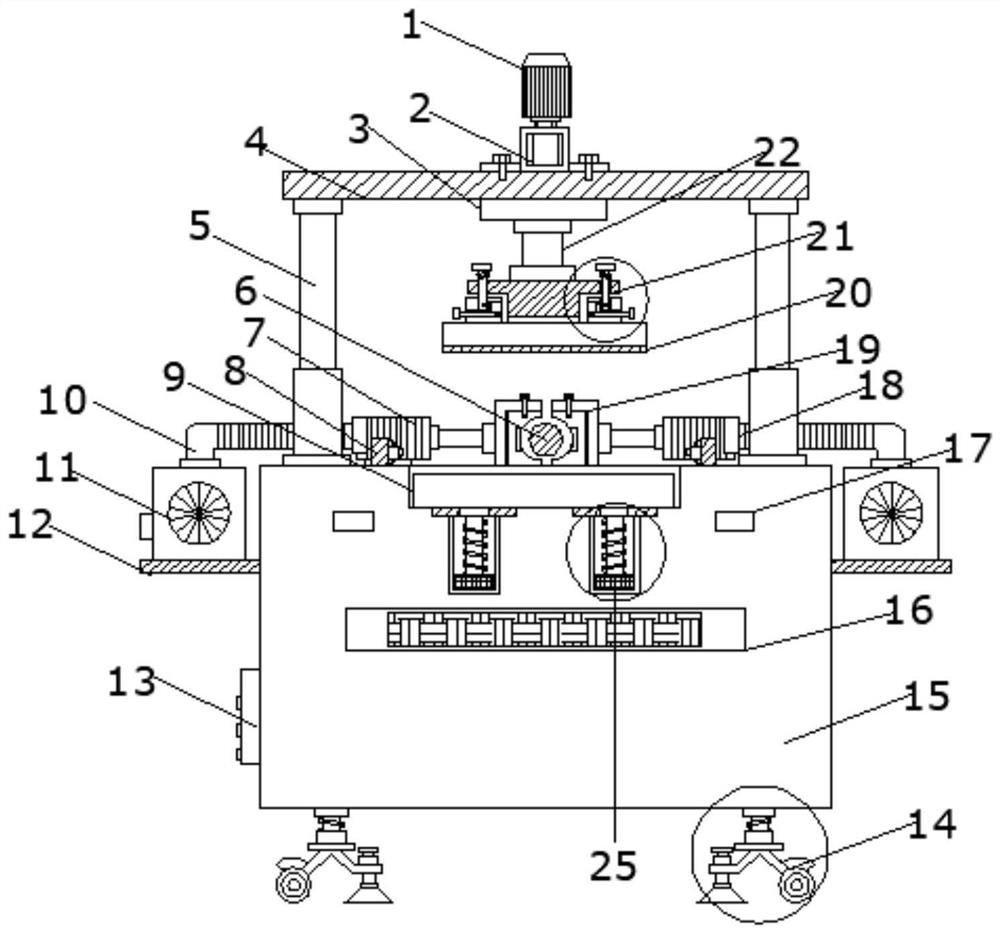
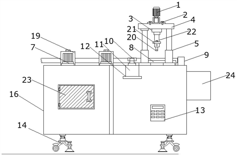
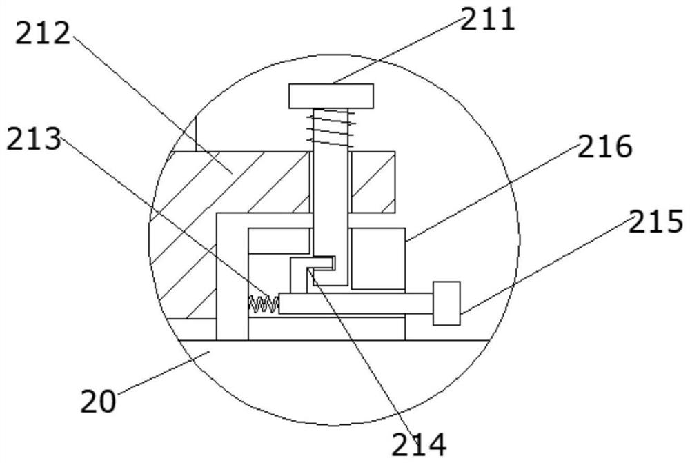
[0032] refer to Figure 1-8, a terminal strip cutting mechanism of an automatic crimping machine, comprising a shock-absorbing mobile-fixing integrated mechanism 14 and a waste pipe 6, the upper end of the shock-absorbing mobile-fixing integrated mechanism 14 is fixedly installed with a strip cutting device body 15, and the strip cutting device body 15 is provided with a power distribution room 23 at the left outer end, and a control room 13 is provided at the right outer end of the material tape cutting device body 15, and an electric push rod 7 is fixedly installed on the upper part of the left s...


PUM


Abstract

The invention discloses an automatic crimping machine terminal material belt cutting mechanism. The automatic crimping machine terminal material belt cutting mechanism comprises a damping, moving and fixing integrated mechanism and a waste material pipe, wherein a material belt cutting device body is fixedly arranged at the upper end of the damping, moving and fixing integrated mechanism; a power distribution room is arranged at the outer end of the left side of the material belt cutting device body, and a control chamber is arranged at the outer end of the right side of the material belt cutting device body; electric push rods are fixedly arranged on the upper portions of the two ends of the left side of the material belt cutting device body, and limiting mechanisms are fixedly connected to the front ends of the electric push rods; supporting seats are welded on the outer sides of the upper portions of the two ends of the material belt cutting device body, and dust collectors are fixedly arranged at the upper ends of the supporting seats; dust suction pipes are fixedly connected to the upper ends of the dust collectors; and dust suction covers are arranged at the front ends of the dust suction pipes. According to the automatic crimping machine terminal material belt cutting mechanism, the waste material pipe is automatically cut, and therefore labor force is saved; and meanwhile, the waste material pipe can be limited, therefore the cutting effect is improved, and functionality is greatly improved.

Description

technical field [0001] The invention belongs to the technical field of crimping equipment in the wire harness industry, in particular to a terminal strip cutting mechanism of an automatic crimping machine. Background technique [0002] In today's electronic communications, new energy vehicles, white goods, aviation, industry and other fields, such as data transmission, image transmission, etc., the required signal propagation speed is getting faster and higher, and the frequency is getting higher and higher. At the same time, the degree of integration is getting higher and higher. Correspondingly, the use of crimping equipment is becoming more and more widespread. With the development of the wire harness industry, more and more connectors use crimping terminals. [0003] The existing crimping terminal waste cutting device generally uses a cutting knife to cut the crimping terminal waste manually, and also needs to manually recycle the terminal waste. The existing crimping te...

Claims


Application Information

Patent Timeline
Patent Type & Authority Applications(China)
IPC IPC(8): B26D1/08B26D3/16B26D7/20B26D7/01B26D7/18B26D7/26H01R43/048
CPCB26D1/08B26D3/16B26D7/01B26D7/1863B26D7/20B26D7/2614B26D2007/013H01R43/048
Inventor 韩林肖萍招陈才华彭全衍
Owner 吉安市联基电子有限公司
Why Eureka
Try Eureka