High-speed ball bearing retainer and high-speed ball bearing of using same

A technology of bearing cages and cages, which is applied to bearing components, shafts and bearings, mechanical equipment, etc., can solve the problems of easily burned bearings and cage valgus, and achieve the effect of high overall rigidity and damage prevention

Pending Publication Date: 2021-05-25
LUOYANG BEARING RES INST CO LTD
View PDF12 Cites 4 Cited by
  • Summary
  • Abstract
  • Description
  • Claims
  • Application Information

AI Technical Summary

Problems solved by technology

[0004] The purpose of the present invention is to provide a high-speed ball bearing cage to solve the technical problem in the prior art that the cage is turned upside down under high-speed rotation and the bearing is easily burned; Bearings to solve the above technical problems

Method used


Image

  • High-speed ball bearing retainer and high-speed ball bearing of using same
  • High-speed ball bearing retainer and high-speed ball bearing of using same
  • High-speed ball bearing retainer and high-speed ball bearing of using same

Examples


specific Embodiment 1

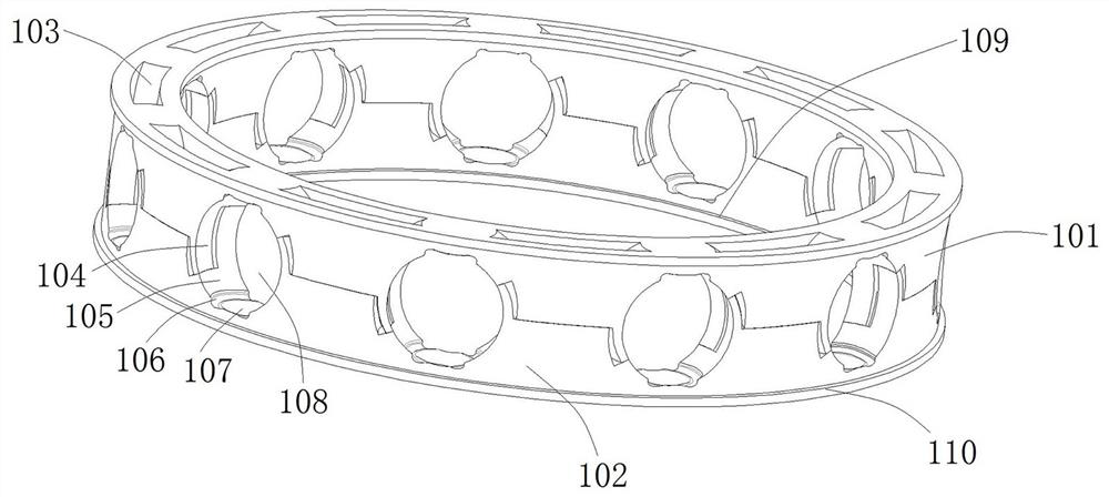
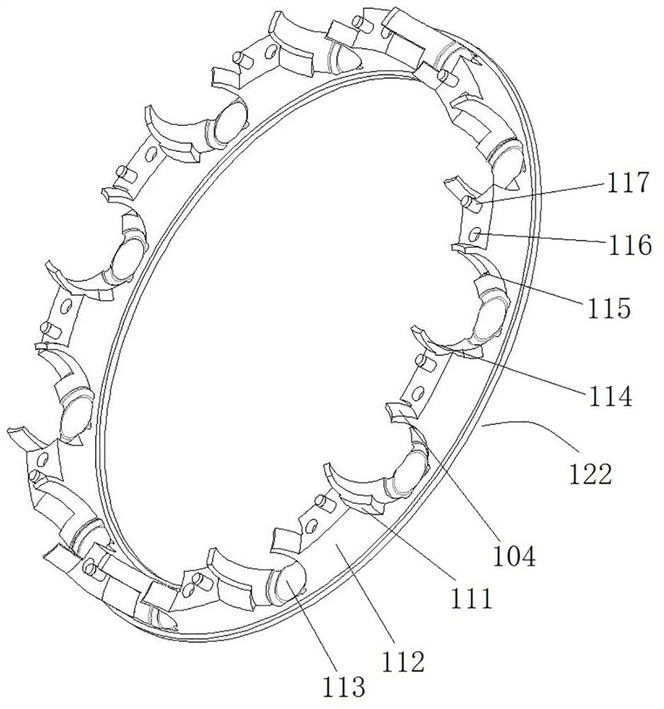
[0066] Such as Figure 1 to Figure 5 As shown, the high-speed ball bearing cage (hereinafter referred to as the cage) of the present invention is integrally injection-molded, and is specifically composed of two identical cages that are injection-molded by thermoplastics, especially polyamide modified plastics, through connection. As a whole, it eliminates the tendency of the lock claws to turn out and deform in the prior art, improves the overall rigidity of the cage, and ensures that under high-speed rotation, the cage will not cause the lock claws to turn up and contact the outer ring of the bearing due to the large centrifugal force , causing a lot of heat to burn the bearings.

[0067] Such as figure 1 As shown, the cage is formed by connecting two separate cages, and the structures of the two cages are the same. For description, in this embodiment, the two cages are defined as the first cage split 101 and the second cage respectively. The cage split 102 is described by ...

Embodiment 1

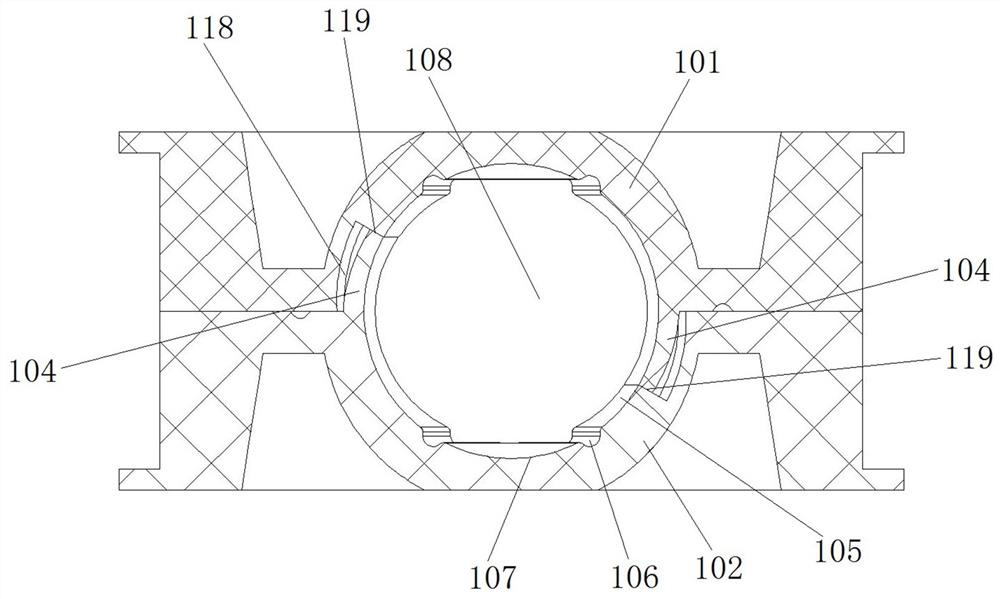
[0080] In Embodiment 1, a pocket oil groove is arranged in the pocket. In this embodiment, the position and shape of the pocket oil groove can be changed according to the actual situation, and the pocket oil groove can also be eliminated.

specific Embodiment 3

[0082] In Embodiment 1, there are protruding rings on the inner and outer sides of the annular body, and oil storage grooves are formed on the inner and outer sides. In this embodiment, the oil reservoir may be formed only on the inner side or only on the outer side. Or the oil storage tank can be canceled.


PUM


Abstract

The invention relates to a high-speed ball bearing retainer and a high-speed ball bearing of using the same. The retainer comprises two retainer split bodies, wherein each retainer split body comprises an annular main body; grooves are evenly distributed in the axial end surface of each annular main body in the circumferential direction of the annular main body; each the annular main body comprise lintels, and connecting columns for fixedly mounting the two annular main bodies together in the axial direction are arranged between the lintels of the two annular main bodies; the retainer comprises a circumferential positioning structure, and the circumferential positioning structure comprises a first positioning structure and a second positioning structure; each positioning structure comprises positioning claws and positioning notches; the positioning notches are formed in the groove walls of the grooves; the positioning claws are arranged at notches of the corresponding grooves, and the positioning claws are inserted into the positioning notches in the axial direction; the groove walls of the grooves are matched with the inner walls of the corresponding positioning claws to form pockets; one axial end of each positioning claw is provided with an inclined stop surface; and the extending directions of the inclined stop surfaces of the positioning claws in the two positioning structures are opposite.

Description

technical field [0001] The invention relates to the technical field of bearings, in particular to a cage for a high-speed ball bearing and a high-speed ball bearing using the cage. Background technique [0002] With the wide application of the new energy vehicle market and the high speed development of drive motors, high-speed deep groove ball bearings are widely used in drive motors. This type of bearing d M The N value has reached 1 million r / min, and the bearings are sealed deep groove ball bearings pre-filled with grease. When the d of this type of bearings M If the N value exceeds 600,000 r / min, the existing design of the bearing cannot meet the working conditions. The existing clip-type cage is shown in the Chinese utility model patent with the authorized announcement number CN208565269U. The cage is generally made of light metal, phenolic resin or plastic, and includes an integral ring-shaped body, which is provided with balls uniformly distributed along the circumfe...

Claims


Application Information

Patent Timeline
Patent Type & Authority Applications(China)
IPC IPC(8): F16C33/38F16C33/44F16C33/66
CPCF16C33/3812F16C33/3875F16C33/3887F16C33/44F16C33/6614F16C33/6629F16C19/06
Inventor 宁仲孙小波张弘毅李建星戴东生任乐
Owner LUOYANG BEARING RES INST CO LTD
Why Eureka
Try Eureka