Tool-free mounting structure of fan connector

An installation structure and connector technology, which is applied to the components, connections, coupling devices, etc. of the connection device, can solve the problems of complicated installation process, unfavorable production efficiency, large plug-in force, etc., to ensure the relative positional relationship, application Convenience and the effect of reducing the insertion force

Active Publication Date: 2021-05-25
SUZHOU LANGCHAO INTELLIGENT TECH CO LTD
View PDF4 Cites 1 Cited by
  • Summary
  • Abstract
  • Description
  • Claims
  • Application Information

AI Technical Summary

Problems solved by technology

[0003] In the prior art, the female head of the fan connector is usually fixed by screw connection, and each fan connector female head needs at least 4 screws for fixing, and tools such as a screwdriver are required for installation and removal, which is not conducive to production efficiency. It is also not conducive to later maintenance, and the installation process is more complicated and cumbersome
[0004] In addition, in the traditional fan connector, in order to ensure the reliability of the contact when the PIN pin is inserted into the female terminal, a contact protrusion is provided on the inner surface of the female terminal, which is realized by the extrusion fit between the PIN needle and the female terminal. The reliability of the contact, although this solution can guarantee the reliability of the contact, but the insertion force is too large, the installation is inconvenient, and it is not convenient for future maintenance

Method used


Image

  • Tool-free mounting structure of fan connector
  • Tool-free mounting structure of fan connector
  • Tool-free mounting structure of fan connector

Examples


Embodiment 1

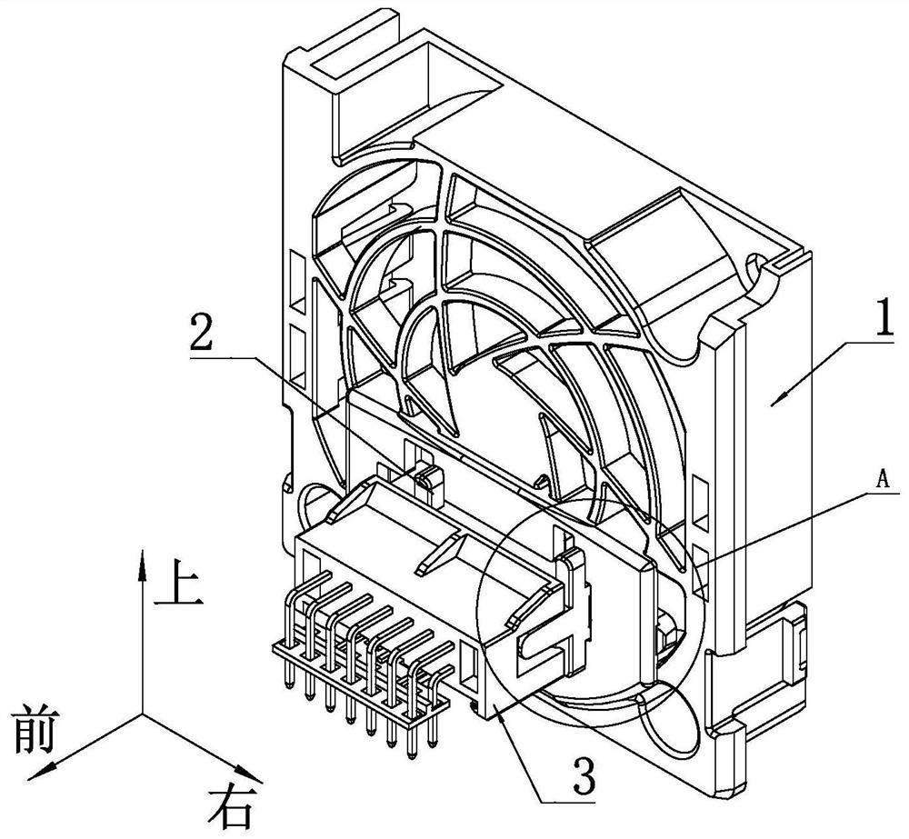
[0050] For the convenience of description, the coordinate system is defined as figure 1 , and the left-right direction is horizontal, the front-back direction is vertical, and the up-down direction is vertical.

[0051] Such as figure 1 As shown, a fan connector tool-free installation structure includes a fan frame 1 for installing a fan and a fan connector arranged on the fan frame 1, and the fan connector includes a male 3 and a female 2, The male connector 3 is fixed on the main board (not shown in the figure), and the female connector 2 is fixed on the fan frame 1 .

[0052] Such as Figure 8 As shown, the female connector 2 of the fan connector includes a female connector body 21, and the front side of the female connector body 21 is provided with a plurality of insertion columns 26 extending longitudinally forward. As a specific embodiment, In this embodiment, a plurality of the insertion posts 26 are arranged in a matrix. A second installation hole extending longitu...

Embodiment 2

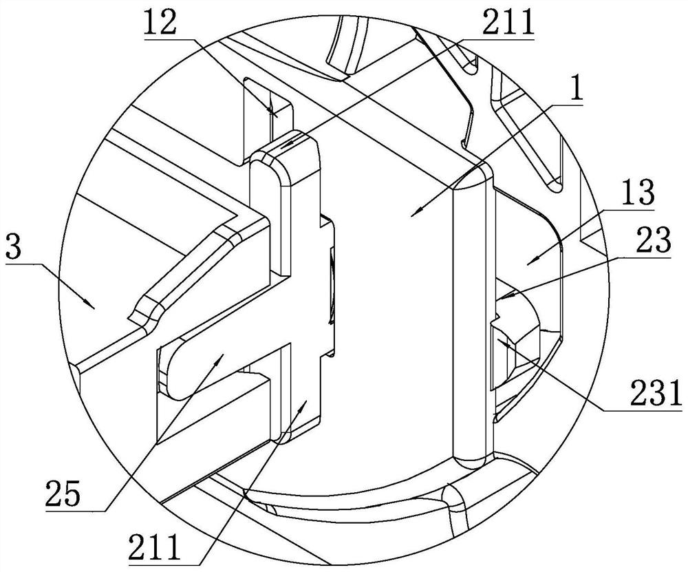
[0072] The limiting structure is a square limiting baffle 221 , and the upper side, lower side, left side and right side of the limiting baffle 221 respectively protrude from the outside of the female connector body 21 . All the other structures are the same as in Embodiment 1.


PUM


Abstract

The invention discloses a tool-free mounting structure of a fan connector, the mounting structure specifically comprises a fan frame and the fan connector, the fan connector comprises a male head and a female head, a first avoiding hole is formed in the front side wall of the fan frame, and the front end of the female head penetrates through the first avoiding hole and extends to the front side of the fan frame. A limiting structure is arranged at the rear end of the female head, a first limiting column is arranged on the portion, located on the front side of the limiting structure, of the female head, the front side wall of the fan frame is clamped between the first limiting column and the limiting structure, and a second receding hole used for allowing the first limiting column to penetrate through is formed in the front side wall of the fan frame. The left end and the right end of the rear side face of the male head are respectively provided with a second guide inclined face matched with the female head. According to the mounting structure, tool-free mounting of the fan connector female head can be achieved, the fixing structure is reliable, the working efficiency can be improved, and later maintenance is facilitated.

Description

technical field [0001] The invention relates to the technical field of server equipment, in particular to a tool-free installation structure of a fan connector. Background technique [0002] Existing servers are designed to improve reliability, and the system fan usually adopts an online thermal maintenance design, that is, the female connector of the fan connector is directly fixed on the fan frame, and the male connector of the fan connector is fixed on the motherboard. [0003] In the prior art, the female head of the fan connector is usually fixed by screw connection, and each fan connector female head needs at least 4 screws for fixing, and tools such as a screwdriver are required for installation and removal, which is not conducive to production efficiency. It is also not conducive to later maintenance, and the installation process is more complicated and cumbersome. [0004] In addition, in the traditional fan connector, in order to ensure the reliability of the cont...

Claims


Application Information

Patent Timeline
Patent Type & Authority Applications(China)
IPC IPC(8): H01R13/631H01R13/639H01R13/405
CPCH01R13/6315H01R13/639H01R13/405
Inventor 刘涛赵乐森王玲燕滕学军马永昊
Owner SUZHOU LANGCHAO INTELLIGENT TECH CO LTD
Why Eureka
Try Eureka