Angle-adjustable multifunctional infusion support

A multi-functional, infusion stand technology, applied in the field of infusion stands, can solve the problems of inconvenient movement and fixation, easy shaking of infusion tubes, inability to adjust the position and height of infusion bottles, etc., and achieve the effect of preventing shaking

Pending Publication Date: 2021-05-28
廖智鹏
View PDF15 Cites 0 Cited by
  • Summary
  • Abstract
  • Description
  • Claims
  • Application Information

AI Technical Summary

Problems solved by technology

[0005] In order to overcome the disadvantages that the infusion stand is inconvenient to move and fix when in use, the position and height of the infusion bottle cannot be adjusted according to the surrounding environment, and the infusion tube is easy to shake during the infusion process, the purpose of the present invention is to provide a method that can adjust the position angle of the infusion stand. Adjustable, the guide of the infusion tube is not easy to shake, it is convenient to move and fix the multifunctional infusion stand with adjustable angle

Method used


Image

  • Angle-adjustable multifunctional infusion support
  • Angle-adjustable multifunctional infusion support
  • Angle-adjustable multifunctional infusion support

Examples


Embodiment 1

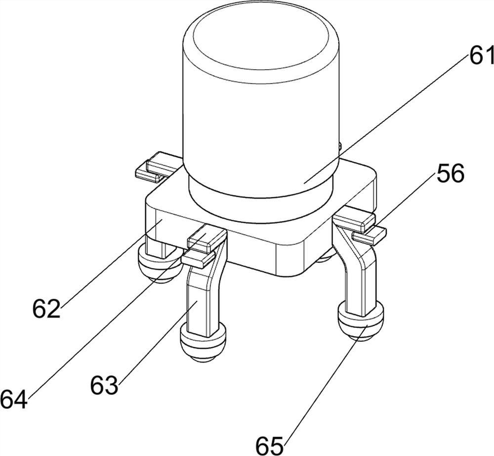
[0034] A multifunctional infusion stand with adjustable angle, such as figure 1 , figure 2 , image 3 and Figure 4 As shown, it includes a base 1 , an adjustment assembly 2 and a clamping assembly 3 , the top of the base 1 is provided with the adjustment assembly 2 , and the upper part of the adjustment assembly 2 is provided with the clamping assembly 3 .

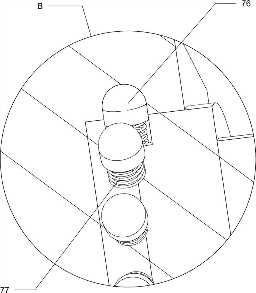
[0035] The adjustment assembly 2 includes a first support rod 21, a first connecting rod 22, a sliding groove 23 and a first rolling ball 24, and four first support rods 21 are evenly arranged on the top of the base 1, and there are connected between the first support rods 21. The first connecting rod 22 is divided into four sections, and every two sections of the first connecting rod 22 are hingedly connected through the sliding groove 23 and the first rolling ball 24 .

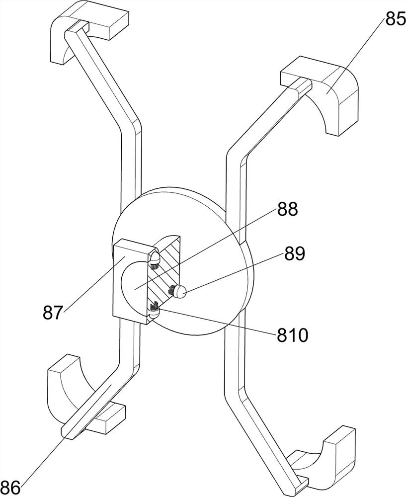
[0036] The clamping assembly 3 includes a second support rod 31, a first clamping block 32, a first spring 33, a slider 34, a first fixing block 35...

Embodiment 2

[0039] On the basis of Example 1, such as figure 1 and Figure 5 to Figure 13 As shown, it also includes a placement assembly 4, and the placement assembly 4 includes a placement plate 41, a first rotating shaft 42, a first telescopic rod 43, a third spring 44, a second fixed block 45, a second rotating shaft 46, a third Fixed block 47, the third rotating shaft 48, wedge-shaped block 49, the fourth spring 410 and rotating plate 411, the first connecting rod 22 on the lowermost side is provided with the first rotating shaft 42 in the left side rotation type, on the first rotating shaft 42 There is a placement plate 41, the bottom of the placement plate 41 is slidingly provided with an installation block, and the left side of the first connecting rod 22 on the lowermost side is symmetrically provided with a second fixed block 45, and the second fixed block 45 is rotatably connected with a second The rotating shaft 46, the second rotating shaft 46 is provided with a sliding slee...


PUM


Abstract

The invention relates to an infusion support, in particular to an angle-adjustable multifunctional infusion support. According to the angle-adjustable multifunctional infusion support, the position angle of the infusion support can be adjusted, an infusion tube is guided and is not prone to shaking, and the infusion support can be conveniently moved and fixed. The angle-adjustable multifunctional infusion support comprises a base and an adjusting assembly, wherein the adjusting assembly is arranged at the top of the base; a clamping assembly which is arranged on the upper portion of the adjusting assembly. The effects that the overall position angle of the infusion support can be adjusted, the infusion tube is guided and is not prone to shaking, and the infusion support is convenient to move and fix are achieved; when a patient is infused, the infusion tube can penetrate through the guide ring to be guided, and influences caused by shaking of the infusion tube when the patient is infused can be effectively prevented.

Description

technical field [0001] The invention relates to an infusion stand, in particular to a multifunctional infusion stand with adjustable angles. Background technique [0002] Infusion poles are indispensable medical devices in hospitals, communities, and elderly care centers. Most of the old-fashioned infusion poles are integral structures. There are floor-type infusion poles, track-type infusion poles, and bedside infusion poles that are used clinically. [0003] At present, some floor-standing infusion stands are heavy and inconvenient to move. It is laborious to manually lift the entire infusion stand when moving; some infusion stands are equipped with universal wheels at the bottom for easy movement, but they are easy to move during use and are not convenient for infusion; Sudden movement of the patient during the infusion process will cause the infusion tube to shake, thereby affecting the patient's infusion; and some infusion stands cannot adjust the position and height of...

Claims


Application Information

Patent Timeline
Patent Type & Authority Applications(China)
IPC IPC(8): A61M5/14
CPCA61M5/1415A61M5/1418
Inventor 廖智鹏
Owner 廖智鹏
Why Eureka
Try Eureka