
Spinning forming method and spinning device for W-shaped metal sealing ring

A technology of spinning forming and sealing rings, which is applied in the field of metal ring manufacturing, can solve problems such as difficult positioning of workpieces, and achieve the effects of simple operation, convenient disassembly, and full consideration

Active Publication Date: 2021-05-28
HUNAN UNIV
View PDF6 Cites 1 Cited by
  • Summary
  • Abstract
  • Description
  • Claims
  • Application Information

AI Technical Summary

Problems solved by technology

[0005] In view of the deficiencies in the prior art, in order to solve the defect that the workpiece positioning is difficult when the W-shaped metal sealing ring is rolled through multiple passes, the present invention provides the following technical solution: a spinning forming method for the W-shaped metal sealing ring, including Follow the steps below:

Method used


Image

  • Spinning forming method and spinning device for W-shaped metal sealing ring
  • Spinning forming method and spinning device for W-shaped metal sealing ring
  • Spinning forming method and spinning device for W-shaped metal sealing ring

Examples


Embodiment 1

[0065]Such asfigure 1 ,2, 8, 9, 10, the present invention provides a rotary press forming method of a W-type metal seal, including the following steps:

[0066]S100. According to the axial cross section of the W-type metal seal, the ring embryoid 1 height of the W-type metal seal, prepared to prepare a height of annular embryo 1;

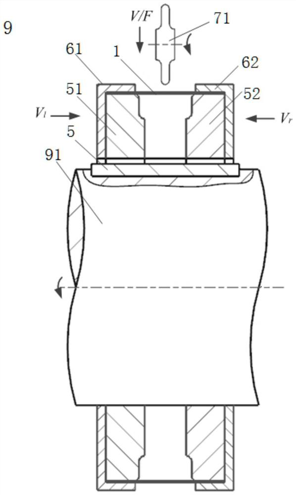
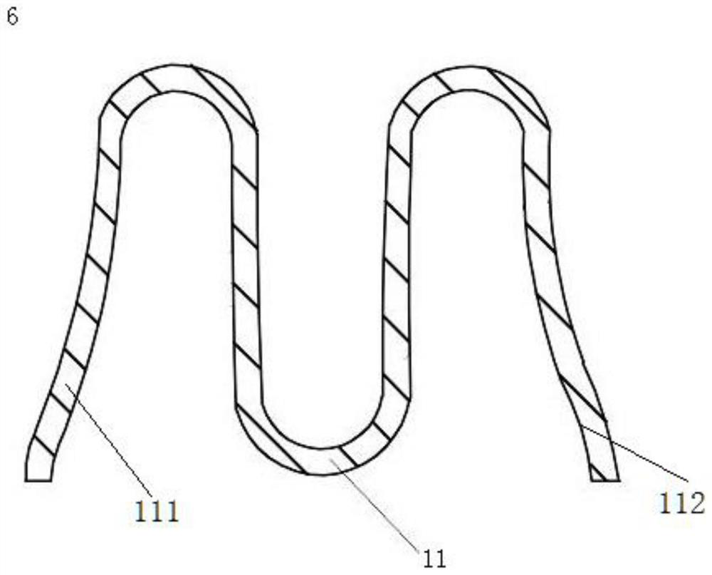
[0067]S200. The radial center of the ring embryo 1 prepared along step S100 is rotated from the annular waist trench portion 11, and the waist trench portion 11 is depressed in the direction of the annular embryo 1 axis;

[0068]S300. The circular embryo 1 is located on the portion of the waist trench portion 11 for rotary press processing, forming a W-type metal seal strike;

[0069]Among them, the waist trench portion 11 is embedded in the cavity of the second core 2 in the circular core groove portion 11 in the circular embryo 1, and the lumbar trench portion 11 is filled. The support ring 3 such that the support ring 3 is clamped to the second mold core 2 to clam...

Embodiment 2

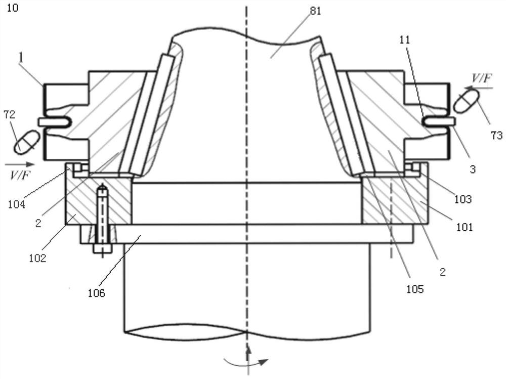
[0107]Such asfigure 1 ,2As shown, the present invention also requires a rotary pressing device for a W-type metal seal sealing, including the waist trench rotation device 9 and two end surface rotation devices for processing the waist groove portion 11 in the annular embryo 1. 10;

[0108]Two-end rotation device 10 includes

[0109]The second rotating shaft 81, the second rotating shaft 81 includes a conical cone;

[0110]The second core 2, the second mold core 2 consists of at least two fed-flap molds, each drive connection with the conical portion of the second rotating shaft 81, respectively; the fed-flap core includes and the waist groove The shape of the groove portion 11 is fitted, and the first side surface of the first bending portion 111 of the W-type metal sealing the halves of the W-shaped metal is adapted to the second curved portion 112 of the W-type metal sealing stroke. The second side of the shape is fitted;

[0111]The second rotary wheel 72, the second rotary wheel 72 always c...


PUM


Abstract

The invention discloses a spinning forming method for a W-shaped metal sealing ring. The method comprises the following steps: S100, the height of an annular blank of the W-shaped metal sealing ring is calculated according to the axial section of the W-shaped metal sealing ring, and the annular blank with the height is prepared; S200, an annular waist groove part is machined in a spinning mode along the radial center of the annular blank prepared in the step S1, and the waist groove part is sunken in the direction where the axis of the annular blank is located; and S300, the parts, located on the two sides of the waist groove part, in the annular blank are subjected to spinning machining, and the W-shaped metal sealing ring is formed. The W-shaped metal sealing ring which is flat, complete and uniform in spinning can be obtained with the method; and a supporting ring is stuffed into the waist groove part of the annular blank, so that the strength of the edge of a second mold core is improved, and the technical problem that the annular blank is difficult to position is effectively solved.

Description

Technical field[0001]The present invention relates to the field of metal ring manufacturing, specifically providing a rotary press forming method of a W-type metal seal, and further relates to a rotary pressing device of a W-type metal seal.Background technique[0002]W-type metal seal yang is a class of axial self-suggestive static sealing structures having new sealing forms and better sealing effects, with good resilience, strong absorption capacity, large deformed, and has good high vibration follower Advantages such as high permeability, long life and better wear resistance, especially suitable for aerospace, high-temperature, vibration, and strong corrosive corrosion in the aerospace.[0003]The formation of the W-type metal seal striped rings is usually used by multi-channel rolling processes, and the rolling forming process is a process of garbled and continuous progressive formation. Although the rolling forming has the advantages of convenient operation, good flexibility, high ...

Claims


Application Information

Patent Timeline
Patent Type & Authority Applications(China)
IPC IPC(8): B21D22/16
CPCB21D22/16
Inventor 龚志辉李伟平
Owner HUNAN UNIV
Learn More