Installation method for fuel cell air compressor under complex distribution of bolt holes

A technology of fuel cell and installation method, applied in metal processing, metal processing equipment, manufacturing tools, etc., can solve problems such as general type difference

Active Publication Date: 2021-05-28
擎能动力科技(苏州)有限公司
View PDF5 Cites 0 Cited by
  • Summary
  • Abstract
  • Description
  • Claims
  • Application Information

AI Technical Summary

Problems solved by technology

[0006] For the first idea, its characteristics are: fast speed, but it can only be used for one type of air compressor. When changing to another type of air compressor, the number and relative positions of the pneumatic pulse assembly tools need to be reset. production (similar to changing molds), therefore, its less versatile

Method used


Image

  • Installation method for fuel cell air compressor under complex distribution of bolt holes
  • Installation method for fuel cell air compressor under complex distribution of bolt holes
  • Installation method for fuel cell air compressor under complex distribution of bolt holes

Examples


Embodiment 1

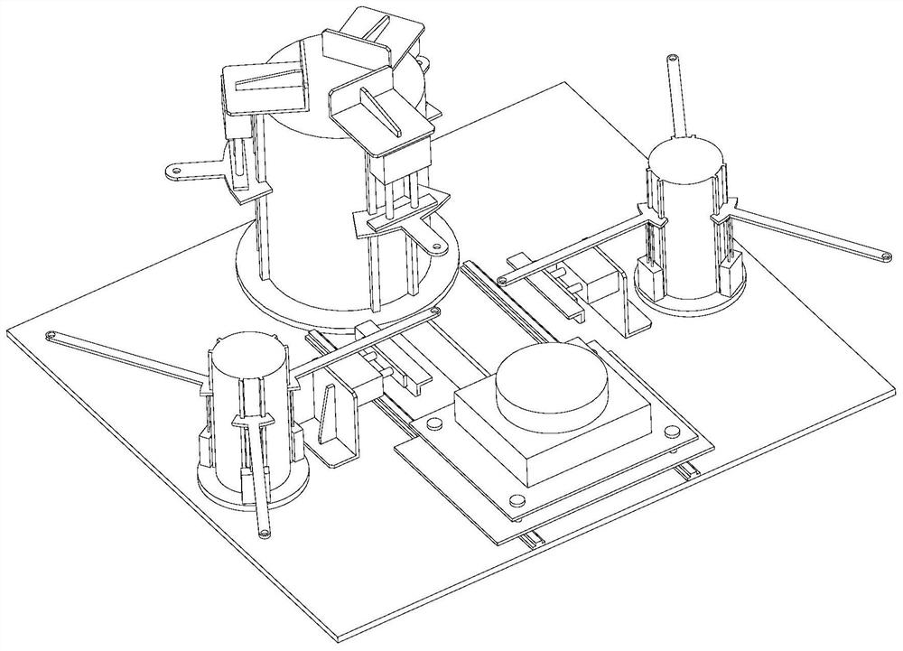
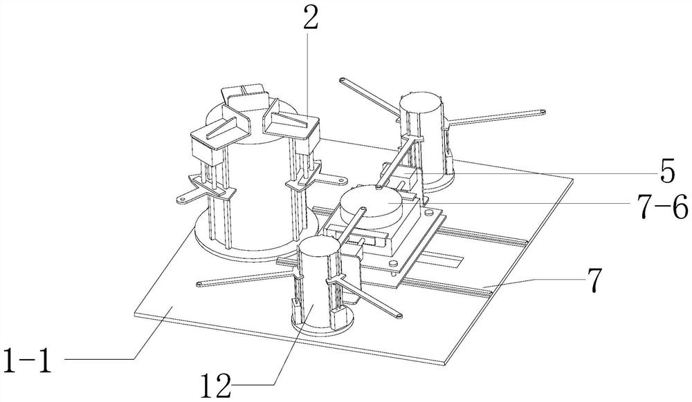
[0170] Embodiment 1, a bolt tightening assembly equipment, including: a frame 1 , a bolt conveying mechanism 2 , a workpiece longitudinal moving mechanism 5 , a workpiece lateral moving mechanism 7 , a tightening mechanism 10 , and two nut conveying mechanisms 12 .

[0171] Wherein, the workpiece lateral movement mechanism 7 includes: workpiece lateral movement telescopic cylinder 7-1, lateral guide rail group 7-2, bearing plate 7-3, connector 7-4, workpiece positioning block placement plate 7-5, workpiece positioning block 7 -6; The horizontal guide rail group 7-2 is fixedly arranged on the platform base plate 1-1, and the telescopic cylinder 7-1 for the lateral movement of the workpiece is placed on the lower side of the platform base plate 1-1. shaped hole, the lower side of the bearing plate 7-3 is fixed with a connecting piece 7-4; the direction of the bar-shaped hole opened by the platform base plate 1-1 is parallel to the direction of the transverse guide rail group 7-2;...

Embodiment 2

[0221] Embodiment two, such as Figure 17 In the case of type A, there are 8 holes (evenly spaced distribution), the internal holes are not provided with threads, and bolt-nut connections are used; type B holes are 6 (evenly spaced), and the internal holes are provided with threaded holes. Threaded hole connections inside workpieces.

[0222] The bolt heads of the bolts to be installed in the A-type hole and the B-type hole have the same size (that is, the bolts in the A-type hole and the B-type hole can be installed by rotation with the same sleeve 10-2).

[0223] face as Figure 17 One problem is: how to determine the installation order of the holes for No. 1 to No. 14 bolts.

[0224] The conventional idea is: No. 1 -> No. 2 -> No. 3 -> No. 4 -> No. 5 -> No. 6 -> No. 7 -> No. 8 -> No. 9 -> No. 10 -> No. 11 -> No. 12 No.->No.13->No.14;

[0225] However, observe Figure 17 The distribution of the bolt holes, obviously, the following scheme is more efficient:

[0226] No....

Embodiment 3

[0259] Embodiment 3: The solution in Embodiment 2 is the optimal solution, but it has a large amount of calculation and is difficult to program.

[0260] A simplified solution is given below:

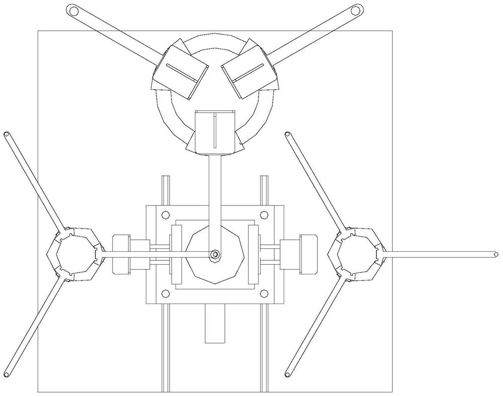
[0261] Take the projection of the center point of the sleeve 10-2 (hereinafter referred to as: the bolt installation position) on the horizontal plane as the origin during installation (the characteristics of the equipment of this application are: the position of the bolt is unchanged during installation, that is, the sleeve is unchanged, Workpiece movement), the direction of the horizontal guide rail group 7-2 is the X direction, and the telescopic direction of the longitudinal telescopic power mechanism is the Y direction (that is, the direction of the longitudinal guide rail is the Y direction);

[0262] In the initial state, the coordinates of each bolt hole where the workpiece is placed on the workpiece positioning block are:

[0263] No. 1 Bolt Hole: (x 1 ,y 1 )

[0264] ... ...


PUM


Abstract

The invention discloses an installation method for a fuel cell air compressor under complex distribution of bolt holes. The method particularly provides three ways. According to the first and second ways, when nuts are not considered, that is, when bolt-workpiece bolt holes are installed, no problem exists, that is, the installation method is suitable for any complex bolt hole distribution. The third way is a universal control method for installation of the bolt, the workpiece and the nut and installation of the bolt and the workpiece. The installation method for the fuel cell air compressor under complex distribution of the bolt holes, the bolt installation efficiency of workpieces is improved.

Description

technical field [0001] The invention relates to the technical field of installation of fuel cell air compressors, in particular to an installation method under complex distribution of bolt holes of fuel cell air compressors. Background technique [0002] The air compressor head, rear cover, and front cover are assembled, which is the last process of air compressor equipment installation. [0003] For the above-mentioned installation equipment, the applicant proposed two ideas: [0004] First, one-time installation, that is, the air compressor head, rear cover, and front cover are assembled with 8 sets of bolt-nut assemblies. Correspondingly, 8 sets of corresponding pneumatic pulse assembly tools are pre-set for one-time installation. [0005] Second, one by one bolt to install. [0006] For the first idea, its characteristics are: fast speed, but it can only be used for one type of air compressor. When changing to another type of air compressor, the number and relative pos...

Claims


Application Information

Patent Timeline
Patent Type & Authority Applications(China)
IPC IPC(8): B23P19/06
CPCB23P19/06
Inventor 尹丛勃宋和国陈雷裴满王振杰
Owner 擎能动力科技(苏州)有限公司
Why Eureka
Try Eureka