
Bottom plate built-in rail damper and its design method

A rail shock absorber, built-in technology, applied in the directions of rails, roads, buildings, etc., can solve the problems of weak lateral restraint ability of products, difficulty in lifting lateral restraint, difficult optimization of rubber layer layout, etc., so as to improve lateral restraint performance, The effect of reducing the probability of permanent deformation and improving safe driving performance

Active Publication Date: 2021-04-16
ZHUZHOU TIMES NEW MATERIALS TECH
View PDF4 Cites 0 Cited by
  • Summary
  • Abstract
  • Description
  • Claims
  • Application Information

AI Technical Summary

Problems solved by technology

[0005] 1. The bottom plate of the existing product is external, and the anchoring connection part is distributed on the outer edge of the bottom plate, that is, the outside of the entire product, which requires a large sleeper space, which has certain limitations for the space-constrained tunnel environment;
[0006] 2. The lateral stiffness of the track damper is mainly provided by the lateral compression deformation of the rubber layer. The existing products have little room for lateral reinforcement due to space constraints, and the lateral restraint ability of the product is relatively weak;
[0007] 3. Larger product outline size requires larger vulcanization molds and higher requirements for vulcanization equipment, which will bring about the purchase cost of large molding equipment;
[0008] 4. The lateral constraint of the bottom plate to the top plate is mainly provided by the rubber layer between the two. The limitation of the existing product structure space makes it difficult to optimize the layout of the rubber layer, and there are great difficulties in improving the lateral constraint

Method used


Image

  • Bottom plate built-in rail damper and its design method
  • Bottom plate built-in rail damper and its design method
  • Bottom plate built-in rail damper and its design method

Examples


Embodiment Construction

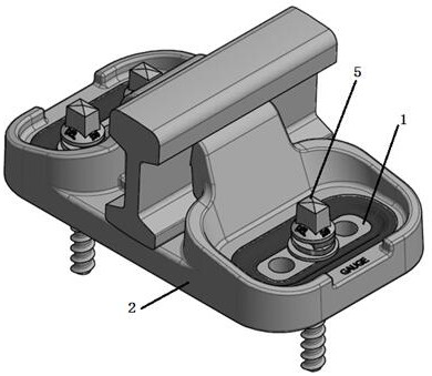
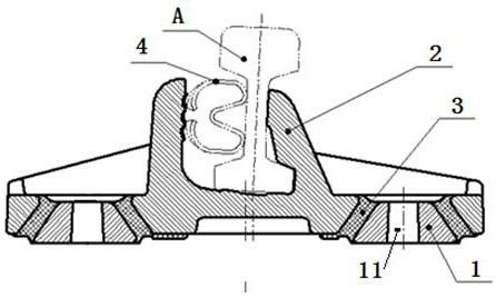
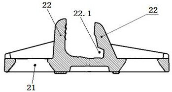
[0031] Combine below Figure 1 to Figure 3 Embodiments of the present invention are described in detail.

[0032] Bottom plate built-in rail shock absorber, including bottom plate 1, top plate 2, rubber layer 3 and elastic buckle clip 4 that cooperates with top plate 2 to press rail A. It is characterized in that the bottom plate 1 is placed in the top plate 2, and the rubber The layer 3 is vulcanized and connected with the top plate 2, and the vulcanized connection surfaces of the bottom plate 1 and the top plate 2 are all inclined surfaces, and the bottom plate 1 is provided with anchoring installation holes 11 for fixing with the sleepers.

[0033] The bottom plate built-in track damper as shown in the figure sets the bottom plate 1 in the top plate 2, that is, the installation position of the track damper is designed inside the product. The size of the bottom plate 1 is smaller, and the vulcanization molding of the top plate 2 is simpler. The requirements for molds, proce...


PUM


Abstract

Bottom plate built-in rail shock absorber and its design method, including bottom plate, top plate, rubber layer and elastic clips that cooperate with the top plate to press the steel rail, characterized in that the bottom plate is placed in the top plate, and vulcanized by the rubber layer and the top plate Connection, the vulcanized connection surfaces of the bottom plate and the top plate are sloped, and the bottom plate is provided with anchor holes for fixing with sleepers. In the present invention, the bottom plate is arranged in the top plate, that is, the installation position of the track damper is designed inside the product, and the requirement for the installation size of the sleeper is reduced. Lateral rigidity, realizing the adjustable stiffness of the rail shock absorber, reducing the probability of permanent deformation of the rubber layer, improving the reliability of the rail shock absorber, simpler vulcanization molding, lower requirements for molds, processes, and equipment, and improving The lateral restraint performance of the rail shock absorber improves the safe driving performance of the road section with small curve radius.

Description

technical field [0001] The invention relates to a bottom plate built-in track damper and a design method thereof, which is used in track sections requiring vibration and noise reduction in various subways and urban light rails, connects rails and sleepers, and effectively isolates vibration and reduces noise. Background technique [0002] With the development of rail transit, more and more cities have invested in the construction of urban rail subway systems. Different design concepts make the types of rails various, which also puts forward better requirements for the adaptability of rail shock absorbers. . Rail shock absorbers can realize load bearing, vibration reduction and ensure driving safety in rail transit lines. In order to save the limited space in the rail transit tunnel, it is required that the rail shock absorber must have appropriate dimensions while meeting the vibration reduction requirements. Rail shock absorbers are connected to the subgrade and rails thr...

Claims


Application Information

Patent Timeline
Patent Type & Authority Patents(China)
IPC IPC(8): E01B19/00
CPCE01B19/003
Inventor 孙照亮谢亮王丹穆忠鑫熊学强刘权
Owner ZHUZHOU TIMES NEW MATERIALS TECH
Learn More