A cooling device with annular waterway based on 3D printing technology

A technology of 3D printing and cooling equipment, applied in cleaning methods and utensils, separation methods, filtration separation, etc., can solve the problems of reducing molding cycle, uneven cooling, easy clogging, etc.

Active Publication Date: 2022-05-06
JIANGSU FOOD & PHARMA SCI COLLEGE
View PDF0 Cites 0 Cited by
  • Summary
  • Abstract
  • Description
  • Claims
  • Application Information

AI Technical Summary

Problems solved by technology

[0002] The cooling of plastic products during injection molding is mainly completed by the cooling water channel of the mold. However, the traditional cooling water channel is manufactured by machining processes such as milling machines. The water channel can only be a cylindrical straight hole, which cannot be completely close to the surface of the injection molded part. The cooling efficiency is low and the cooling is uneven. , leading to long injection molding cycle and large product deformation. The water channel of the conformal water channel mold workpiece manufactured by 3D printing can be evenly distributed with the shape of the product, reducing the molding cycle. With the continuous improvement of the printing process and the continuous improvement of printing accuracy, 3D Printing of conformal waterway workpieces is becoming more and more widely used, but since 3D printed conformal waterways belong to additive manufacturing, the inside of the waterway is not smooth and there will be many folds, and dirt is easy to hide in the folds, and as the use time of the waterway increases , the conformal waterway is full of scale, which is easy to block and affect the cooling effect, and it is difficult to clean the conformal waterway with general methods, so the service life is short

Method used


Image

  • A cooling device with annular waterway based on 3D printing technology
  • A cooling device with annular waterway based on 3D printing technology
  • A cooling device with annular waterway based on 3D printing technology

Examples


Embodiment Construction

[0017] In order to make the purpose, technical solutions and advantages of the embodiments of the present invention clearer, the technical solutions in the embodiments of the present invention will be clearly and completely described below in conjunction with the drawings in the embodiments of the present invention. Obviously, the described embodiments It is a part of embodiments of the present invention, but not all embodiments. Based on the embodiments of the present invention, all other embodiments obtained by persons of ordinary skill in the art without creative efforts fall within the protection scope of the present invention.

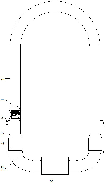
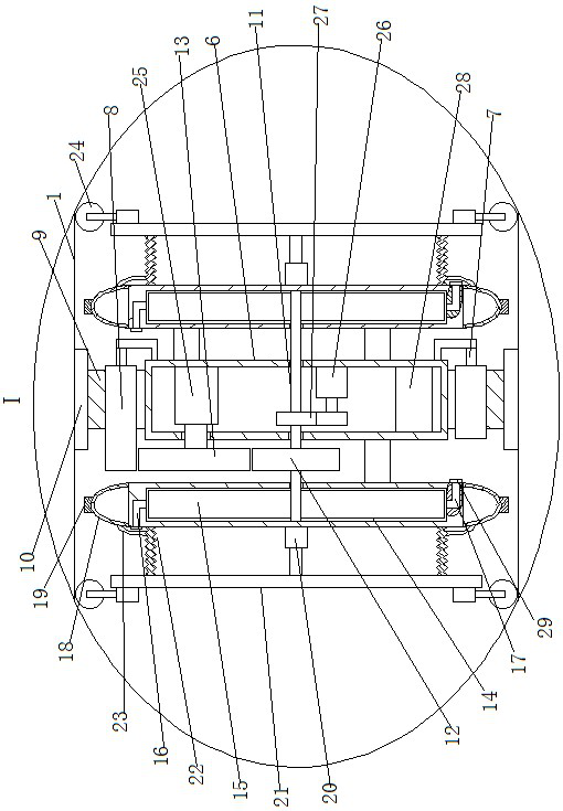
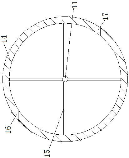
[0018]A cooling device with an annular waterway based on 3D printing technology, as shown in the figure, includes a conformal waterway 1, which is set inside the injection mold, and both ends of the conformal waterway 1 are connected with a parking cavity 2, The parking chamber 2 is connected to the conformal waterway 1 through an inclined plane, ...


PUM


Abstract

A cooling device with an annular waterway based on 3D printing technology, including a conformal waterway. There are parking cavities at both ends of the conformal waterway. The outer end of the parking cavity is connected to a reversing water pump. There is a cleaning device for the inner wall of the waterway. The cleaning device for the inner wall of the waterway includes an installation box. The outside of the installation box is connected to the first shaft. There is a first gear outside the first shaft. A baffle is arranged on the wall, and a guide wheel assembly is arranged on the outside of the baffle. In the present invention, there are parking cavities at both ends of the conformal waterway, and the water flow can pass through the gap between the waterway inner wall cleaning device and the parking cavity to form a water cycle to take away the heat in the mold, and the water flow can push the waterway inner wall cleaning device along the Waterway walking can also drive the blades to scrape off the dirt on the inner wall of the waterway through the water flow, and the cooling effect of the conformal waterway can be further improved by reversing the direction of the water pump.

Description

technical field [0001] The invention belongs to the field of cooling equipment, in particular to a cooling equipment with annular water channels based on 3D printing technology. Background technique [0002] The cooling of plastic products during injection molding is mainly completed by the cooling water channel of the mold. However, the traditional cooling water channel is manufactured by machining processes such as milling machines. The water channel can only be a cylindrical straight hole, which cannot be completely close to the surface of the injection molded part. The cooling efficiency is low and the cooling is uneven. , leading to long injection molding cycle and large product deformation. The water channel of the conformal water channel mold workpiece manufactured by 3D printing can be evenly distributed with the shape of the product, reducing the molding cycle. With the continuous improvement of the printing process and the continuous improvement of printing accuracy...

Claims


Application Information

Patent Timeline
Patent Type & Authority Patents(China)
IPC IPC(8): B29C64/20B01D35/02B08B9/043B29C45/73B33Y30/00
CPCB29C64/20B29C45/73B01D35/02B08B9/0436B33Y30/00
Inventor 刘月云
Owner JIANGSU FOOD & PHARMA SCI COLLEGE
Why Eureka
Try Eureka