Cable pulling auxiliary device with self-locking structure

An auxiliary device and self-locking technology, which is applied in the direction of transportation and packaging, thin material handling, cable laying equipment, etc., can solve the problems affecting the efficiency and quality of cable handling, the shaking of the supporting shaft cable tray, the shaking of the cable roll, etc., and achieve high efficiency. And stabilize the cable work, reduce shaking and vibration, and reduce the effect of rotating the center of gravity

Active Publication Date: 2021-05-28
国网甘肃省电力公司超高压公司
View PDF20 Cites 0 Cited by
  • Summary
  • Abstract
  • Description
  • Claims
  • Application Information

AI Technical Summary

Problems solved by technology

[0003] 1. In the existing cable structure, most of them are equipped with independent support shafts to support the cable reels. In this way, scattered auxiliary structures will not only increase the operating workload of the staff, but also increase the management burden of the staff.
[0004] 2. When the cable reel is suspended in the air by a jack or other driving device, it is easy to cause the shaking of the cable reel, which in turn causes safety risks such as scratching; on the other hand, the high center of the cable reel will also affect the stability of the payout
[0005] 3. The function of the support shaft is mainly to provide the support force for the rotation of the cable reel. In the existing operation, in order to facilitate the penetration of the support shaft, the outer diameter of the support shaft is usually smaller than the support through hole of the cable reel (there is usually a hole on the cable reel for The cable reel that runs through the support shaft), so that under the action of its own weight, the suspended cable reel cannot be coaxial with the support shaft. Off-axis rotation, so it is very easy to cause the support shaft or the cable reel to shake or jump, which will inevitably affect the stability of the cable pay-off
[0006] 4. There is no structure capable of braking the rotation of the cable reel on the pull wire support frame, so that under the action of external force, the cable reel is likely to release too many cables, which will consume extra manpower and time to process it ( winding back or discarding), it is bound to affect the efficiency of cable payout
[0007] 5. Since the cables are mostly stored and transported in the form of coils, the cables will be bent when unwinding, which will greatly affect the efficiency and quality of the subsequent processing of the cables by the operator.

Method used


Image

  • Cable pulling auxiliary device with self-locking structure
  • Cable pulling auxiliary device with self-locking structure
  • Cable pulling auxiliary device with self-locking structure

Examples


Embodiment 1

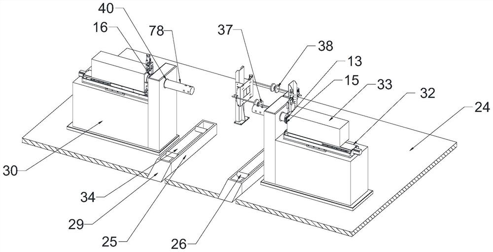
[0066] Such as Figure 1 to Figure 17 As shown, the pull wire auxiliary device with a self-locking structure includes a pull wire support frame 24;

[0067] The backguy support frame 24 has the support slide rail 25 that two intervals are arranged, is provided with the support accommodating groove 34 that runs through the top of support slide rail 25 on the support slide rail 25, is installed on the support slide rail 25 along its slide rail conveying direction and is installed with two intervals. The limit roller 26, the limit roller 26 can rotate relative to the support pulley 25;

[0068] The rear end of the support slide rail 25 is connected with an entry support 29, the top surface of the entry support 29 is inclined, and the height of the entry support 29 gradually decreases towards the direction away from the support slide rail 25;

[0069] The stay wire support frame 24 also has two mounting frames 30 respectively positioned at the outer sides of the two supporting sl...

Embodiment 2

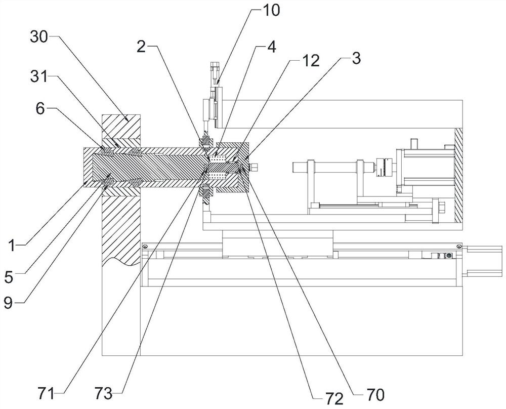
[0085] This embodiment makes the following further limitations on the basis of Embodiment 1: the locking assembly includes a shaft body 1 and an end cap 3 threaded on the outer end of the shaft body 1, and a sliding rod movable groove 2 is opened in the shaft body 1, and the shaft body 1 The outer end of the body 1 is also provided with a relief port 12 communicating with the movable groove 2 of the slide bar;

[0086] The slide bar movable groove 2 is connected with the slide bar 5 which can slide axially along the shaft body 1 in the slide bar movable groove 2 through the slide bar elastic member 4;

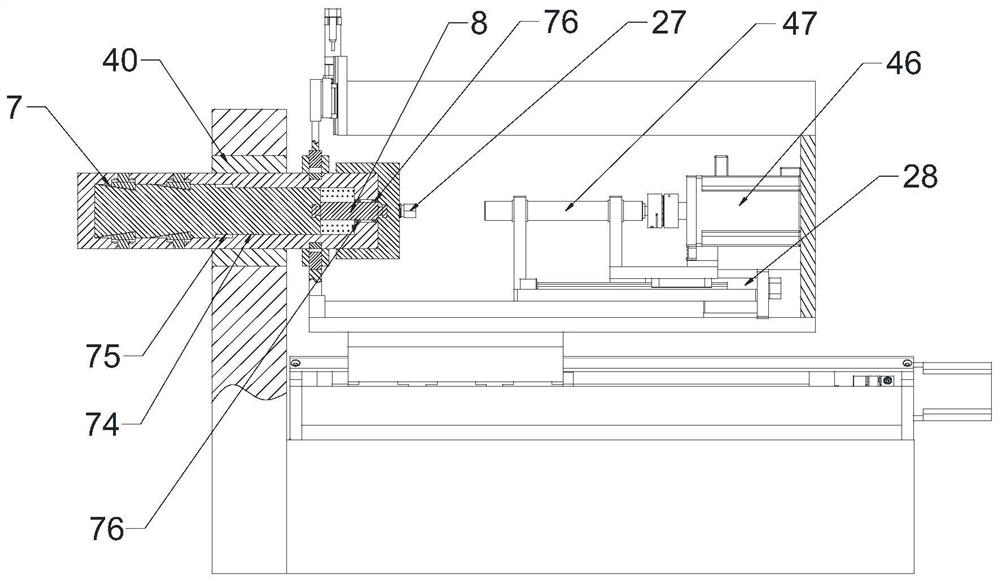
[0087] The slide bar 5 is provided with several sets of sliding notch groups evenly distributed along the slide bar 5 ring direction, each sliding notch group includes at least one sliding notch 7, the groove bottom of the sliding notch 7 is arranged on an inclined plane, and the sliding notch The groove depth of the port 7 gradually increases from the inner end to the outer en...

Embodiment 3

[0105] In order to realize the interlocking movement of the moving frame 33 to the locking assembly, this embodiment makes the following further limitations on the basis of Embodiment 2: the outer surface of the shaft body 1 is provided with a moving ring assembly;

[0106] The moving ring assembly has two moving rings 13 arranged at intervals, and a moving transmission ring groove 14 is formed between the two moving rings 13;

[0107] The moving frame 33 is provided with a transmission member 15 that can be placed in the moving transmission ring groove 14 and can rotate relative to the transmission ring groove 14 .

[0108] In this embodiment, through the cooperation of the transmission member 15 and the moving transmission ring groove 14 , the moving frame 33 can drive the shaft body 1 to move, and the relative rotation between the shaft body 1 and the moving frame 33 can be realized.

[0109] Such as Figure 11 to Figure 12 As shown, the transmission member 15 may include ...


PUM


Abstract

The invention discloses a cable pulling auxiliary device with a self-locking structure. The cable pulling auxiliary device comprises a cable pulling supporting frame. The cable pulling supporting frame is provided with two supporting sliding rails which are arranged in a spaced mode, supporting containing grooves are formed in the supporting sliding rails, two limiting idler wheels are installed on the supporting sliding rails, and the limiting idler wheels can rotate relative to supporting pulleys. The rear ends of the supporting sliding rails are connected with entering supports, and the top end faces of the entering supports are inclined. The cable pulling supporting frame is further provided with two mounting frames located on the outer sides of the two supporting sliding rails correspondingly. Mounting through holes are formed in the mounting frames in a penetrating manner, and a locking assembly capable of axially moving and circumferentially rotating relative to the mounting through holes is mounted in one mounting through hole. Each mounting frame is further provided with a mounting frame driving assembly. According to the cable pulling auxiliary device, through the arrangement of the two limiting idler wheels and the locking assembly, on one hand, the rotating gravity center of a cable reel can be effectively lowered, and then efficient and stable cable pulling work can be guaranteed; and on the other hand, the locking assembly is integrated on the cable pulling supporting frame so that the workload of operators can be reduced.

Description

technical field [0001] The invention belongs to the technical field of cable construction, and in particular relates to a wire pulling auxiliary device with a self-locking structure. Background technique [0002] Cable is a necessary material for the construction of power lines, and it is usually wound on a cable drum to enter the construction site in rolls. In order to facilitate the laying-out of cables, the support shaft is usually used to penetrate the cable roll (the cable has been wound on the cable reel), the cable roll is set on the support shaft, and then the support shaft is placed on the wire support frame, and then through a jack or other The drive unit raises the support shaft or the cable support frame to suspend the cable coil, so that the cable can be released. But existing support device (stay wire support frame and support shaft) has following problem: [0003] 1. In the existing cable structure, most of them are equipped with independent support shafts t...

Claims


Application Information

Patent Timeline
Patent Type & Authority Applications(China)
IPC IPC(8): B65H49/32B65H67/02B65H57/14B65H49/34B65H63/00H02G1/06
CPCB65H49/325B65H49/324B65H67/02B65H57/14B65H49/34B65H63/00H02G1/06B65H2701/34
Inventor 刘珏伶黄浩鹏
Owner 国网甘肃省电力公司超高压公司
Why Eureka
Try Eureka