Built-in permanent magnet motor roller

A permanent magnet motor and roller technology, applied in electrical components, electromechanical devices, hoisting devices, etc., can solve the problems of poor motor protection, easy damage to the motor, and poor practicability of the hoist, and increase the number of winding layers. , the effect of increasing the traction height and increasing the width of the support

Active Publication Date: 2021-05-28
ANHUI UNIV OF SCI & TECH
View PDF8 Cites 0 Cited by
  • Summary
  • Abstract
  • Description
  • Claims
  • Application Information

AI Technical Summary

Problems solved by technology

[0003] However, a kind of built-in permanent magnet motor roller in the current market has the following problems during use. a. The rollers in the traditional built-in permanent magnet motor roller are all of one-piece structure, which cannot be deformed, that is, the outer wall of the roller can be wound around for traction The number of turns and layers of the rope cannot be adjusted according to the actual use requirements, resulting in poor practicability of the whole hoist; b. The traditional built-in permanent magnet motor drums are all driven by motors arranged on the side wings of the drum, which exposes the motor to the external environment Among them, when the motor is impacted by external force, the motor is easy to be damaged, and the protection for the motor is poor

Method used


Image

  • Built-in permanent magnet motor roller
  • Built-in permanent magnet motor roller
  • Built-in permanent magnet motor roller

Examples


Embodiment Construction

[0025] The embodiments of the present invention will be described in detail below with reference to the accompanying drawings, but the present invention can be implemented in many different ways defined and covered by the claims.

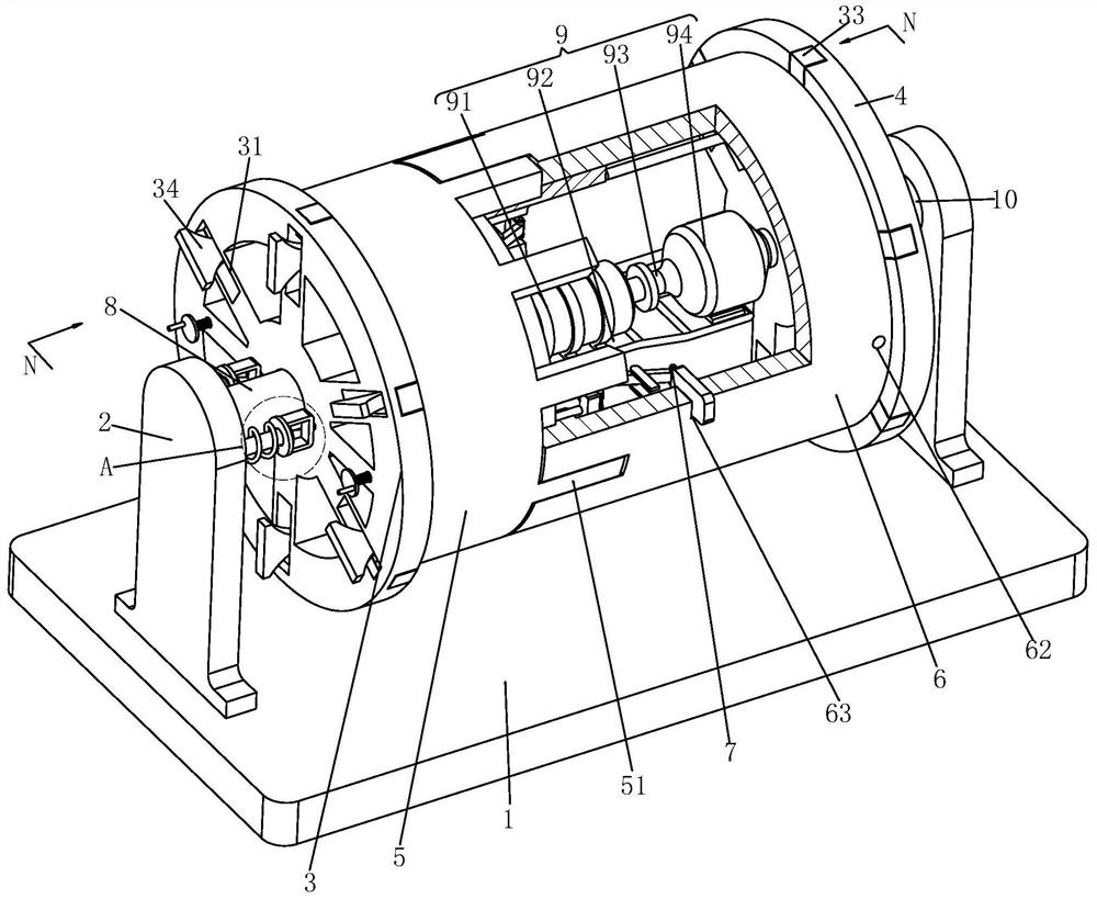
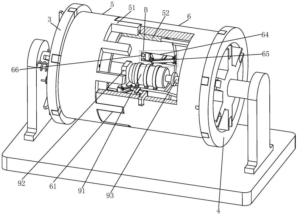
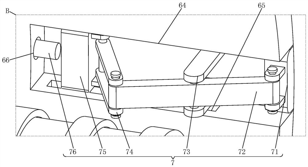
[0026] Such as Figure 1 to Figure 7 As shown, a built-in permanent magnet motor drum includes a supporting base plate 1, a supporting side plate 2, a driven rotating side drum 3, an active rotating side drum 4, a first bobbin 5, a second bobbin 6, and a lateral The driving mechanism 7, the first supporting shaft 8, the driving mechanism 9 and the second supporting shaft 10, the top of the supporting bottom plate 1 is symmetrically equipped with supporting side plates 2, and the side walls of the two supporting side plates 2 are respectively welded A support shaft 8 and a second support shaft 10, the outer wall of the first support shaft 8 is sleeved with the driven rotation side cylinder 3, the outer wall of the second support shaft 10 is sleeved w...


PUM


Abstract

The invention relates to a built-in permanent magnet motor roller which comprises a bearing bottom plate, supporting side plates, a driven rotating side cylinder, a driving rotating side cylinder, a first winding cylinder, a second winding cylinder, a transverse driving mechanism, a first supporting shaft, a driving mechanism and a second supporting shaft. The supporting side plates are symmetrically mounted at the top of the bearing bottom plate, the first supporting shaft and the second supporting shaft are welded to the side walls of the two supporting side plates correspondingly, the outer wall of the first supporting shaft is connected with the driven rotating side cylinder in a sleeved manner, the outer wall of the second supporting shaft is connected with the driving rotating side cylinder in a sleeved manner, the first winding cylinder is welded to the side wall of the driven rotating side cylinder, the second winding cylinder is welded to the side wall of the driving rotating side cylinder, and the driving mechanism is arranged at the end of the first supporting shaft. According to the built-in permanent magnet motor roller, a motor can be effectively protected, the situation that the motor is damaged is avoided, the requirements of operation at different heights can be met by changing the maximum number of winding turns and the maximum number of overlapping layers of traction ropes of the first winding cylinder and the second winding cylinder, and practicability is higher.

Description

technical field [0001] The invention relates to the technical field of material conveying equipment, in particular to a built-in permanent magnet motor roller. Background technique [0002] Elevator is one of many material conveying equipment. It is usually composed of a drum, a traction rope and a supporting fixed pulley. One end of the traction rope is bolted to the outer wall of the drum, and then the traction rope is reversely changed through the supporting fixed pulley. Finally, the motor drives the drum to wind up the traction rope. The other end of the traction rope hangs the object for vertical transportation. The hoist is mainly used in fields such as ore mining and method construction. Through the characteristics of vertical material transportation of the hoist, the material at the lower level can be quickly transported to the upper level. The hoist drum is the core component of the hoist, which directly affects the hoisting height of the traction rope. [0003]...

Claims


Application Information

Patent Timeline
Patent Type & Authority Applications(China)
IPC IPC(8): B66D1/12B66D1/30B66D1/28H02K7/10
CPCB66D1/12B66D1/30B66D1/28H02K7/10
Inventor 郭永存王爽胡坤寇子明李德永
Owner ANHUI UNIV OF SCI & TECH
Why Eureka
Try Eureka