
Road pile for road construction

A technology for road construction and road piles, applied in the field of road piles for road construction, can solve problems such as affecting the use of road piles, uneven surface of road piles, road pile damage, etc., and achieves the effect of improving service life and improving crash resistance.

Inactive Publication Date: 2021-05-28
赵晓琳
View PDF10 Cites 2 Cited by
  • Summary
  • Abstract
  • Description
  • Claims
  • Application Information

AI Technical Summary

Problems solved by technology

[0002] Road pile is a common name for columnar roadblocks. Road pile is a common road safety facility used to isolate motor vehicle lanes and non-motor vehicle lanes, or set up non-motor vehicle lanes to restrict motor vehicles. Road piles are mainly used in urban intersection lanes , Expressway maintenance, traffic police law enforcement, hotels and other places, there are many types of road piles. In terms of control methods, there are roughly 4 types: fixed, fixed and movable type, fixed pre-embedded movable type, semi-automatic lifting type, Fully automatic type, because the road piles are set on the road and there are too many vehicles on the road, collisions often occur. The road piles that are collided often have uneven surface of the road piles, and even after a strong impact, due to the road piles The bottom is fixed, and the road pile will break directly from the installation position with the ground, causing serious damage to the road pile and affecting the use of the road pile

Method used


Image

  • Road pile for road construction
  • Road pile for road construction
  • Road pile for road construction

Examples


Embodiment 1

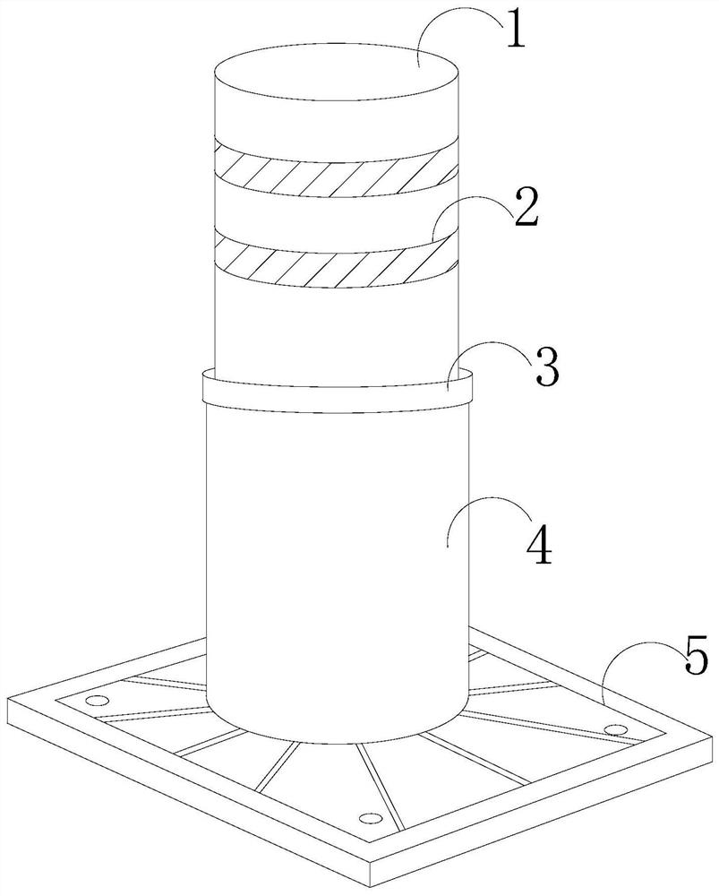
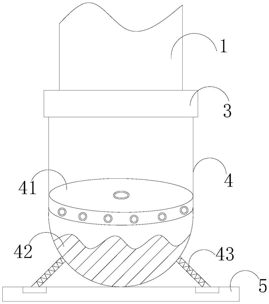
[0025] Such as Figure 1-Figure 5 As shown, the present invention provides a road pile for road construction, and its structure includes a lifting rod body 1, a light strip 2, a control base 3, a fixed column 4, and a mounting chassis 5, and the mounting chassis 5 is mechanically connected with a fixed column 4, The fixed column 4 is provided with a control base 3, the control base 3 is connected to the lifting rod body 1, the surface of the lifting rod body 1 is provided with two light strips 2, and the fixed column 4 is provided with a swing device 41 , load-bearing lead weight 42, connection extension spring 43, described swinging device 41 is located on the weight-bearing lead weight 42, and described connection extension spring 43 is provided with four, is the bottom outside that the circumference is evenly distributed on fixed column 4, and described connection One end of the extension spring 43 is connected to the fixed column 4, and the other end is connected to the in...


PUM


Abstract

The invention discloses a road pile for road construction, which structurally comprises a lifting rod body, two light-emitting strips, a control base, a fixed upright post and a mounting chassis, the fixed upright post is mechanically connected to the mounting chassis, the control base is arranged on the fixed upright post, the control base is connected with the lifting rod body, and the two light-emitting strips are arranged on the surface of the lifting rod body. The fixed stand column is provided with a swing device, a load bearing lead block and four connecting tension springs, the swing device is arranged on the load bearing lead block, the four connecting tension springs are circumferentially and uniformly distributed on the outer side of the bottom of the fixed stand column, one end of each connecting tension spring is connected with the fixed stand column, and the other end of each connecting tension spring is connected with the mounting base plate. According to the road pile, the connecting position between the fixed stand column and the mounting base plate is spherical. A load bearing lead block is arranged in the fixed stand column, a connecting spring is arranged between the fixed stand column and the mounting base plate, and when the road pile is strongly collided, the fixed stand column shakes back and forth in a tumbler state, so that indirect damage to equipment due to the fact that the road pile directly falls to the ground after being collided is avoided, and the service life of the equipment is prolonged.

Description

technical field [0001] The invention relates to the field of road construction, in particular to a road pile for road construction. Background technique [0002] Road pile is a common name for columnar roadblocks. Road pile is a common road safety facility used to isolate motor vehicle lanes and non-motor vehicle lanes, or set up non-motor vehicle lanes to restrict motor vehicles. Road piles are mainly used in urban intersection lanes , Expressway maintenance, traffic police law enforcement, hotels and other places, there are many types of road piles. In terms of control methods, there are roughly 4 types: fixed, fixed and movable type, fixed pre-embedded movable type, semi-automatic lifting type, Fully automatic type, because the road piles are set on the road and there are too many vehicles on the road, collisions often occur. The road piles that are collided often have uneven surface of the road piles, and even after a strong impact, due to the road piles The bottom is f...

Claims


Application Information

Patent Timeline
Patent Type & Authority Applications(China)
IPC IPC(8): E01F13/04
CPCE01F13/048
Inventor 赵晓琳
Owner 赵晓琳
Learn More