
Electrical energy system comprising fuel cells

A fuel cell and electric energy technology, applied in the field of electric energy systems, can solve problems such as excess weight and insignificant installation space, and achieve the effects of avoiding indirect damage, reducing system complexity, and saving weight and structural space

Pending Publication Date: 2021-03-16
AUDI AG
View PDF3 Cites 0 Cited by
  • Summary
  • Abstract
  • Description
  • Claims
  • Application Information

AI Technical Summary

Problems solved by technology

As a result, additional costs
Furthermore, the two switch-on and switch-off boxes require not insignificant installation space and result in an excess weight of several kilograms

Method used


Image

  • Electrical energy system comprising fuel cells
  • Electrical energy system comprising fuel cells

Examples


Embodiment Construction

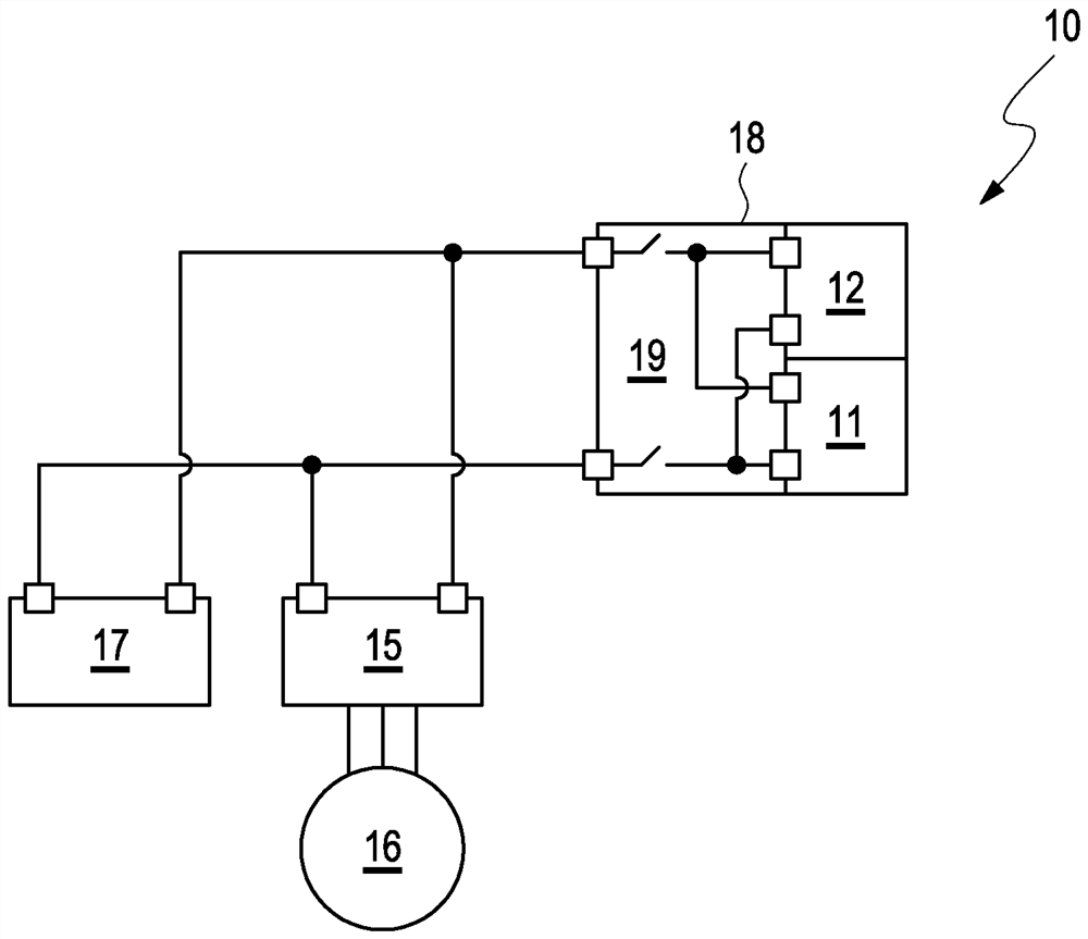
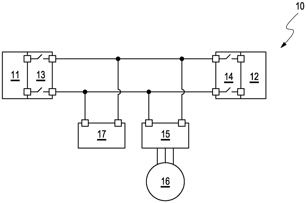
[0026] figure 1 A schematic diagram of a prior art energy system is shown, in which loads 15, 16, 17 are coupled. The energy system 10 includes a fuel cell 11 and an HV battery 12 as energy sources. The fuel cell and the HV battery are respectively connected to the traction circuit via associated on and off units 13, 14, the fuel cell 11 is connected to the traction circuit via the FCJB (Fuel Cell Junction Box) 13 and the HV battery 12 is connected via the BJB ( The battery junction box) 14 is connected with the traction circuit. Connected to the traction circuit are pulse inverter 15 and electric motor 16 and other HV components 17, such as fuel cell auxiliary assembly, charger, 12VDC / DC converter, HV heater, electric air conditioning compressor, etc. .

[0027] figure 2 A schematic diagram of an embodiment of an energy system 10 according to the invention is shown, in which loads 15 , 16 , 17 are connected. The energy system 10 comprises a fuel cell 11 and a HV bat...


PUM


Abstract

The invention relates to a fuel cell-containing electrical energy system and to a method for operating an electrical energy system for a motor vehicle.

Description

technical field [0001] The invention relates to an electrical energy system comprising a fuel cell and to a method for operating an electrical energy system for a motor vehicle. Background technique [0002] The energy system of a fuel cell vehicle usually comprises, in addition to the fuel cell circuit, an HV battery circuit (traction circuit) from which HV loads such as, for example, one or more pulse inverters or electric drives connected to pulse inverters are supplied. The motor and also other loads such as heaters or other fuel cell auxiliary assemblies feed. [0003] A device is known from DE 10 2009 027 220 A1 for supplying an electric drive for a motor vehicle with an energy network which is connected to the drive and has a fuel cell unit and an energy store, wherein , the fuel cell unit is connected to the energy storage. A first converter is arranged between the fuel cell unit and the drive, and a second converter is arranged between the energy store and the dri...

Claims


Application Information

Patent Timeline
Patent Type & Authority Applications(China)
IPC IPC(8): H01M50/574H01M16/00B60L58/40
CPCH01M16/006H01M2220/20H01M2250/20B60L58/40B60L50/75Y02T90/40Y02T10/70Y02E60/50Y02E60/10H01M50/574H01M50/579H01M10/425H01M2010/4271
Inventor M·布罗伊M·席德迈尔
Owner AUDI AG
Learn More