
Battery system and method for determining battery module voltages

A battery system and battery technology, applied in the field of battery systems, to achieve the effect of avoiding indirect damage

Active Publication Date: 2013-08-14
ROBERT BOSCH GMBH +1
View PDF4 Cites 0 Cited by
  • Summary
  • Abstract
  • Description
  • Claims
  • Application Information

AI Technical Summary

Problems solved by technology

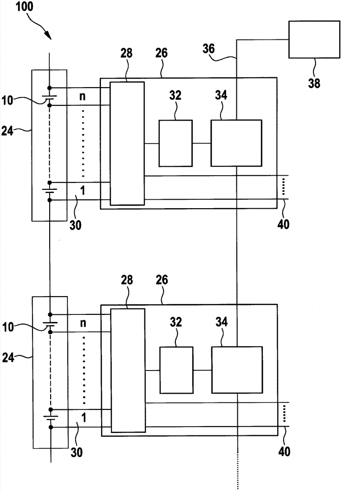
[0011] A disadvantage of the architecture shown is that the central control device 38 communicates directly only with the uppermost cell voltage detection unit 26 and each cell voltage detection unit 26 is connected downstream

Method used


Image

  • Battery system and method for determining battery module voltages
  • Battery system and method for determining battery module voltages
  • Battery system and method for determining battery module voltages

Examples


Embodiment Construction

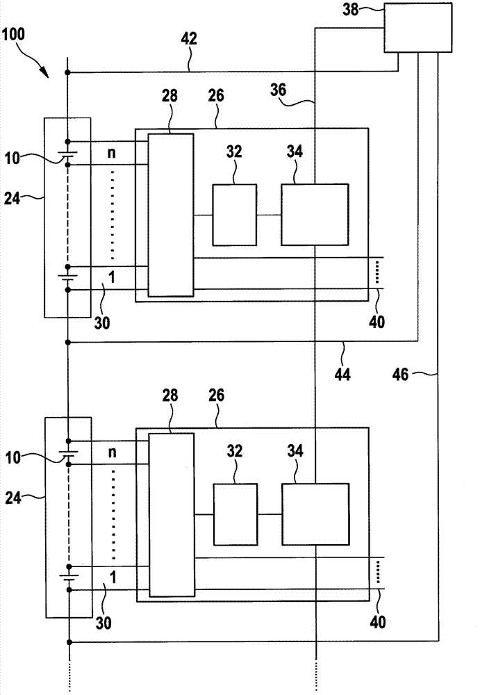
[0031] image 3A battery system 100 according to a first preferred embodiment variant of the invention is shown. A plurality of battery cells 10 are connected in series and are each integrated in a module 24 . In the multiplexer 28 , the cell voltages of the individual battery cells 10 are collected there and fed via an analog-to-digital converter 32 and a gateway 34 into a common communication bus 36 . The voltage analysis is carried out by microcontroller 38 in a known manner.

[0032] exist image 3 Two modules 24 each having a plurality of battery cells 10 are shown by way of example. Embodiments not shown, however, can also connect a plurality of modules 24 in series with each other or additionally in parallel.

[0033] Module measurement leads 42 , 44 , 46 are associated with each module 24 . The module measuring lines 42 , 44 , 46 tap the voltage applied to the individual modules 24 and feed it to a central control unit, in the exemplary embodiment a microcontrolle...


PUM


Abstract

A battery system (100) is proposed having at least two modules (24) which comprise a multiplicity of battery cells (10), with each module (24) being associated with a cell voltage detection unit (26) which is connected to a central controller (38) via a common communication bus (36). The invention provides for each module (24) to additionally comprise a module voltage detection unit which is connected to the central controller (38) and is designed to separately detect the voltage of the associated module (24). The invention also relates to a method for determining battery module voltages in a battery system (100), wherein each of the cell voltage detection units (26) determines the voltages of the individual battery cells (10), and the determined voltage values are transmitted via a common communication bus (36) to a central control (38), with a module voltage additionally being detected separately and being supplied to the central controller (38), for each module (24). A motor vehicle having a battery system (100) is also provided, wherein the battery system (100) is connected to a motor vehicle drive system.

Description

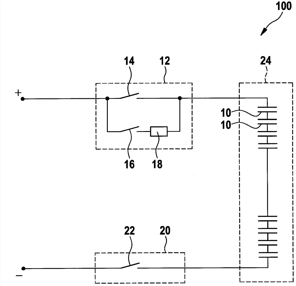
technical field [0001] The invention relates to a battery system, a method for determining the voltage of battery modules of the battery system, and a motor vehicle having a battery system according to the invention. Background technique [0002] In the future, more and more new types of battery systems will be used, both in static applications and in vehicles such as hybrid vehicles and electric vehicles, and high requirements are placed on the reliability of such battery systems. [0003] The background to this high demand is that a failure of the battery system can lead to failure of the entire system. In electric vehicles, for example, failure of the traction battery can lead to so-called "squatting". In addition, failure of the battery may also pose safety-related problems. In wind power plants, for example, batteries are used in order to protect the plant from impermissible operating states in strong winds by means of blade control. [0004] The schematic circuit di...

Claims


Application Information

Patent Timeline
Patent Type & Authority Applications(China)
IPC IPC(8): H01M10/48G01R31/36H01M50/569
CPCY02E60/12H01M10/482H04Q2209/84H04Q2209/86H02J7/0029G01R31/362H01M10/052G01R31/3658H04Q9/00Y02T10/7011G01R31/3835G01R31/396Y02E60/10H01M50/569Y02T10/70
Inventor A·博施J·费策尔S·布茨曼H·芬克M·朗
Owner ROBERT BOSCH GMBH
Learn More