Multi-seat type fast-assembly wellhead device
A technology of wellhead devices and valves, which is applied in wellbore/well valve devices, wellbore/well parts, earthwork drilling and production, etc., which can solve the problems that valves cannot be replaced quickly, so as to save the time and process of replacing valves, save physical effect
- Summary
- Abstract
- Description
- Claims
- Application Information
AI Technical Summary
Problems solved by technology
Method used
Image
Examples
specific Embodiment approach 1
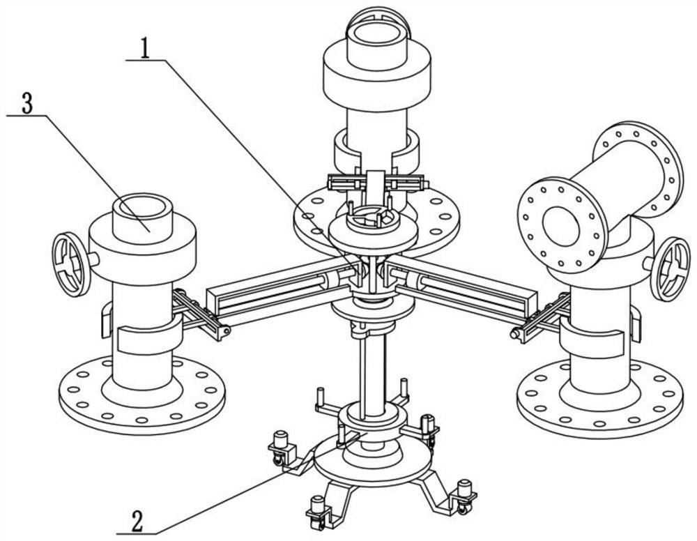
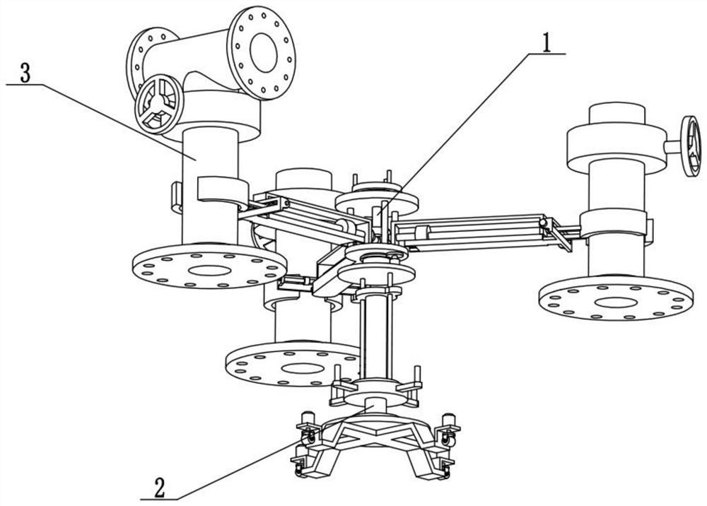
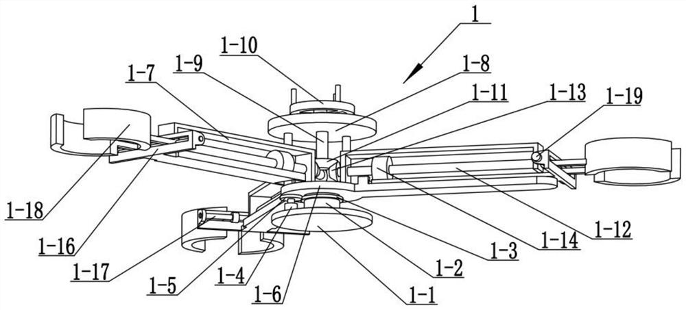
[0024] The following describes this embodiment in conjunction with the drawings. The present invention relates to the technical field of wellhead devices, more specifically, a multi-seat quick-installation wellhead device, including a valve conversion clamping mechanism 1, and the valve conversion clamping mechanism 1 includes a clamping beam 1-16, clamping screw rod 1-17, arc clamping arm 1-18 and clamping motor 1-19, multiple clamping screw rods 1-17 are respectively rotatably connected to multiple clamping beams 1-16 , each clamping screw rod 1-17 is threadedly connected with two arc-shaped clamping arms 1-18, and multiple clamping motors 1-19 are respectively fixedly connected to multiple clamping beams 1-16. Each clamping screw rod 1-17 is respectively fixedly connected to the output shafts of multiple clamping motors 1-19.
[0025] The clamping screw rod 1-17 fixed on the output shaft is driven by the clamping motor 1-19 to rotate. When the clamping screw rod 1-17 rotate...
specific Embodiment approach 2
[0027] The present embodiment will be described below in conjunction with the drawings. This embodiment will further explain Embodiment 1. Each of the clamping beams 1-16 is provided with a slideway, which is used to cooperate with two arc-shaped clamping arms 1-18. Sliding contact on the clamping crossbeam 1-16; limit the movement track of the two arc clamping arms 1-18, keep the two arc clamping arms 1-18 to move horizontally, and ensure to drive the valve to move horizontally.
specific Embodiment approach 3
[0029] The present embodiment will be described below in conjunction with the drawings. This embodiment will further illustrate the second embodiment. The valve switching clamping mechanism 1 also includes a base 1-1, a rotating shaft 1-2, a ring rack 1-3, and a rotating motor. 1-4, rotating gear 1-5, bifurcated flat plate 1-6, sliding plate 1-15 and T-shaped chute 1-20, a plurality of T-shaped chutes 1-20 are arranged on bifurcated flat plate 1-6, A plurality of sliding plates 1-15 are respectively slidably connected in a plurality of T-shaped chute 1-20, and a plurality of clamping beams 1-16 are respectively fixedly connected to the outer ends of a plurality of sliding plates 1-15, and the bifurcated flat plate 1- 6 is fixedly connected to the top of the rotating shaft 1-2, the bottom of the rotating shaft 1-2 is connected to the base 1-1 in rotation, the ring rack 1-3 is fixedly connected to the rotating shaft 1-2, and the rotating gear 1-5 Fixedly connected on the output ...
PUM
 Abstract
Description
Claims
Application Information
 - R&D
- Intellectual Property
- Life Sciences
- Materials
- Tech Scout
- Unparalleled Data Quality
- Higher Quality Content
- 60% Fewer Hallucinations
Browse by: Latest US Patents, China's latest patents, Technical Efficacy Thesaurus, Application Domain, Technology Topic, Popular Technical Reports.
© 2025 PatSnap. All rights reserved.Legal|Privacy policy|Modern Slavery Act Transparency Statement|Sitemap|About US| Contact US: help@patsnap.com


