Protection automatic control device and method for dam tension wire endpoint and measuring point

A technology of automatic control device and tensioning wire, applied in the direction of measuring device, instrument, etc., can solve the problems such as the inability to flexibly adjust the steel wire protection grid, the larger hole of the wire mesh, and the inability to meet the measurement requirements, so as to achieve good protection and monitoring. Effect, low equipment cost, overcoming the effect of limited structure size

Pending Publication Date: 2021-05-28
XIAN THERMAL POWER RES INST CO LTD
View PDF0 Cites 1 Cited by
  • Summary
  • Abstract
  • Description
  • Claims
  • Application Information

AI Technical Summary

Problems solved by technology

When a fixed steel wire grid is used for protection, due to the displacement of the measuring point or the measured object, the tension line body is stuck when it touches the steel wire grid, and the line body is in a non-free state, which affects the range of movement of the measuring point components and The measurement range and the measured displacement are distorted. The steel wire protection grid cannot be flexibly adjusted according to the actual displacement of the tension line body. If the aperture is too large, it will not meet the protection requirements. The contact jamming cannot meet the actual measurement requirements; in addition, the steel wire protection grid cannot avoid the wire contact problem during manual adjustment, and after multiple adjustments, the wire mesh holes become larger, which cannot meet the protection requirements

Method used


Image

  • Protection automatic control device and method for dam tension wire endpoint and measuring point
  • Protection automatic control device and method for dam tension wire endpoint and measuring point
  • Protection automatic control device and method for dam tension wire endpoint and measuring point

Examples


Embodiment Construction

[0041] The technical solutions of the present invention will be further described in detail below in conjunction with the accompanying drawings and specific embodiments.

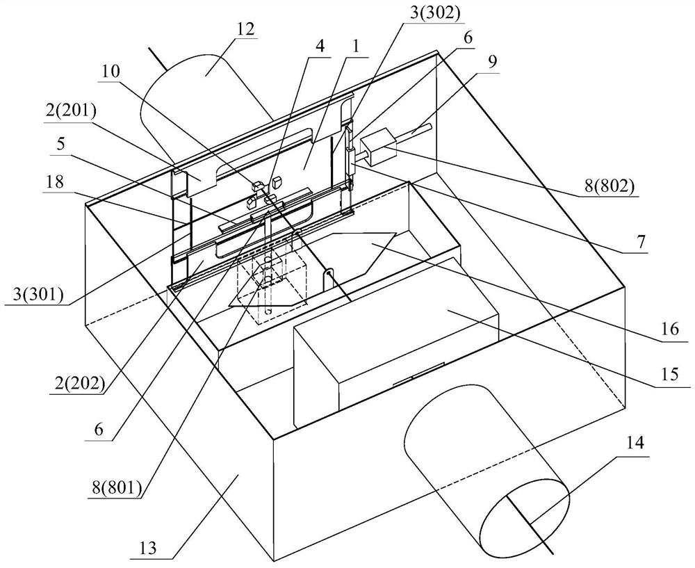
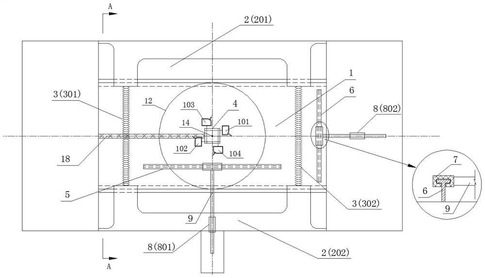
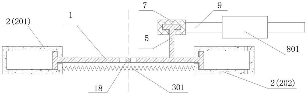
[0042] refer to Figure 1 to Figure 4 : the protective automatic control device of the dam drawing line end point and measuring point of the present invention comprises a direct drive protective plate, a follow-up protective plate 2, a compression spring 3, a wire hole 4, a lower guide rail 5, a side guide rail 6, a guide groove 7, Linear motor, thrust connecting rod 9, laser switch sensor 10 and control module 11.

[0043] Among them, the follow-up protection plate is divided into an upper follow-up protection plate 201 and a lower follow-up protection plate 202, which are closed on the left and right sides and the side of the direct drive protection plate. In the middle of the protective plate 201 and the lower follow-up protective plate 202; the bottom of the direct drive protective plate is connected wi...


PUM


Abstract

The invention discloses a protection automatic control device and method for a dam tension wire end point and a measuring point. The device comprises a direct drive protection plate, a follow-up protection plate, a thrust connecting rod, a control module and the like. T-shaped edges are arranged on the upper and lower edges of the direct drive protection plate, and the bottoms are connected through compression springs to form a nested structure; a square wire passing hole is formed in the middle of the direct drive protection plate, laser switch sensors are arranged around the direct drive protection plate, and T-shaped guide rails are arranged below and on the side faces of the direct drive protection plate and matched with guide grooves formed in the ends of the thrust connecting rods to achieve transmission. During working, displacement of the dam body causes the tension wire to trigger the laser switch, the control module controls the linear motor drive to directly drive the protection plate to move, the line body is automatically prevented from being in contact with the edge, the free state of the line body is kept, and meanwhile alarm work of the dam monitoring system is achieved under the limit displacement control logic. The device is high in working stability and simple and clear in control logic, and has good protection and monitoring effects on the tension wire system.

Description

technical field [0001] The invention belongs to the technical field of operation and maintenance of a dam safety monitoring system, and in particular relates to a protective automatic control device and method for the end point and measuring point of a dam tension line. Background technique [0002] The dam safety monitoring system is an important facility for monitoring the operation behavior of hydraulic structures and discovering potential safety hazards in time. As an integral part of the dam safety monitoring system, the tension line system is widely used in the deformation observation of the crest, corridor, slope and other parts of the linear dam. The free-hanging projected straight line is used as the baseline to measure the lateral displacement offset value of the dam measuring point, and the deformation monitoring results of the tension line are usually used as one of the important basis for grasping the deformation law of the dam and evaluating the safety and stab...

Claims


Application Information

Patent Timeline
Patent Type & Authority Applications(China)
IPC IPC(8): G01B21/02G01B21/32
CPCG01B21/02G01B21/32
Inventor 程帅汪俊波南江裴海林陈仓米珂兰昊焦盼德郭巍李晓博
Owner XIAN THERMAL POWER RES INST CO LTD
Why Eureka
Try Eureka