Scarifier for modern agricultural cultivation
A technology for scarifiers and scarifier knives, applied in agricultural machinery and implements, agriculture, applications, etc., can solve the problems of difficult to rotate the knife, stuck in the sand, easy to leak water and fees, etc.
- Summary
- Abstract
- Description
- Claims
- Application Information
AI Technical Summary
Problems solved by technology
Method used
Image
Examples
Embodiment 1
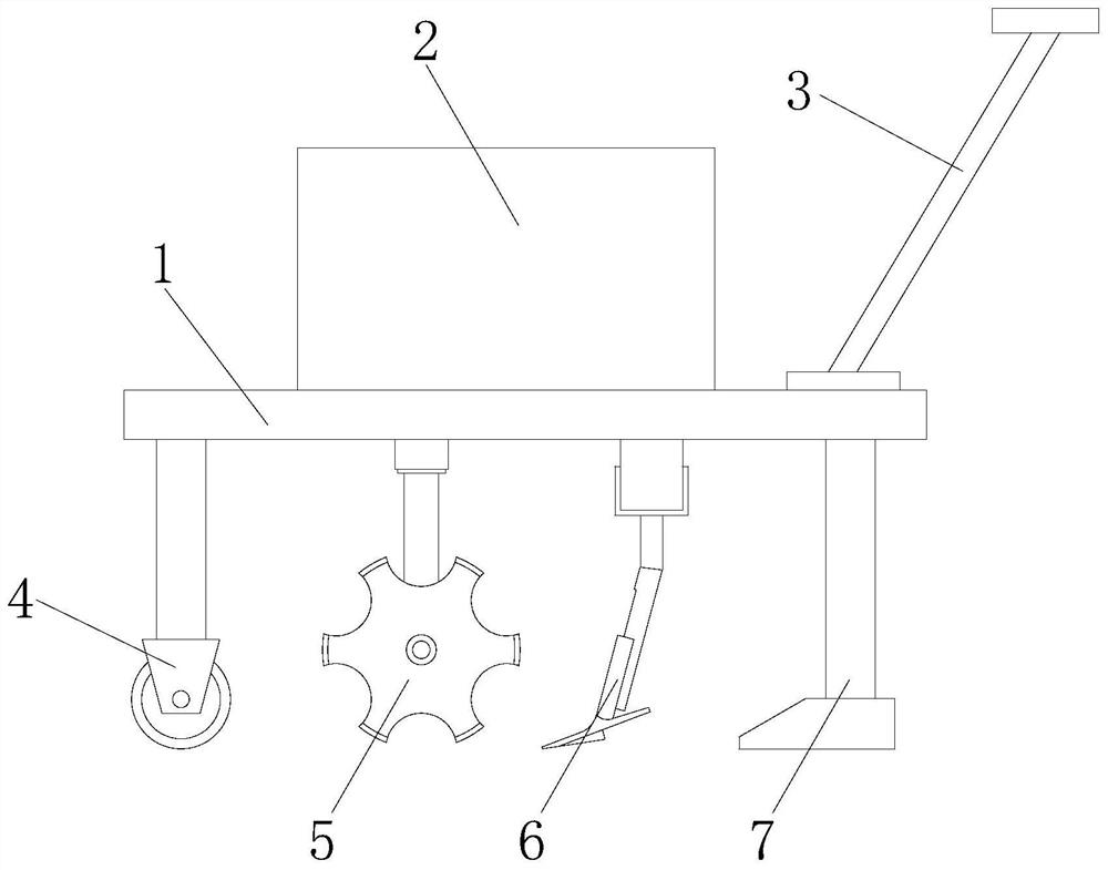
[0022] as attached figure 1 to attach Figure 4 Shown:
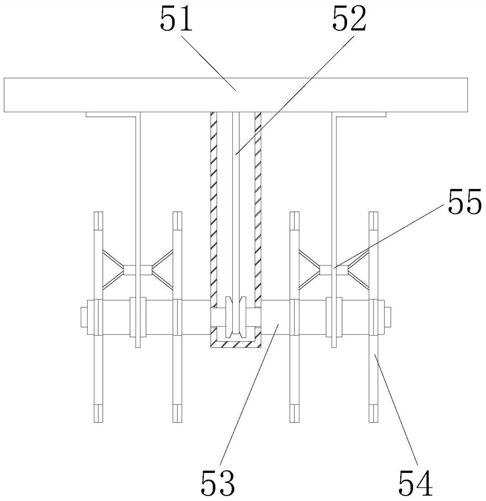
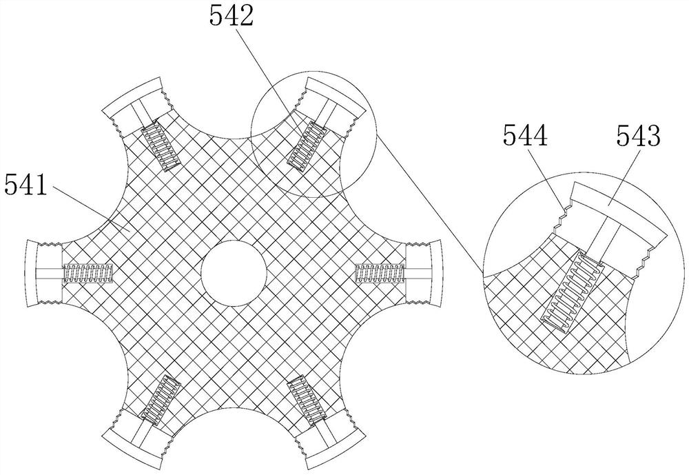
[0023] The present invention is a kind of ripper for modern agricultural cultivation, its structure comprises mobile car 1, driving box 2, push handle 3, drive wheel 4, ripper knife 5, ripper bar 6, support foot 7, described mobile car 1. A drive box 2 is fixedly installed in the middle of the upper surface, and the right end surface of the mobile vehicle 1 is welded to the lower end of the push handle 3. The lower left end of the mobile vehicle 1 is provided with a drive wheel 4, and the scarifier knife 5 is installed on the mobile vehicle 1. bottom, and the ripper knife 5 is connected to the internal transmission of the drive box 2, the right end of the ripper knife 5 is provided with a ripper bar 6, and the upper end of the ripper bar 6 is welded to the bottom of the mobile vehicle 1, and the upper end of the leg 7 is welded to the The bottom surface on the right side of the mobile car 1, the ripper knife 5 includes...
Embodiment 2
[0029] as attached Figure 5 to attach Figure 7 Shown:
[0030] Wherein, the suspension device 55 includes a suspension support plate 551, a wall scraping mechanism 552, and a bearing 553. The lower end of the suspension support plate 551 is provided with a bearing 553, and the drive shaft 53 runs through the inside of the bearing 553 with a clearance fit. The outer surface of the plate 551 is welded with a scraping mechanism 552, and the scraping mechanism 552 is in conflict with the outer side of the upper end of the cutter device 54. There are two scraping mechanisms 552, and they are symmetrically installed on the left and right sides of the suspension support plate 551 , which is conducive to simultaneously resisting the surface of the contacting rotor 41a at both ends of the suspension support plate 551, and scraping off the clay on both sides of the outer surface of the contacting rotor 41a.
[0031] Wherein, the wall scraping mechanism 552 includes a hinge plate 52a...
PUM
 Abstract
Description
Claims
Application Information
 - R&D
- Intellectual Property
- Life Sciences
- Materials
- Tech Scout
- Unparalleled Data Quality
- Higher Quality Content
- 60% Fewer Hallucinations
Browse by: Latest US Patents, China's latest patents, Technical Efficacy Thesaurus, Application Domain, Technology Topic, Popular Technical Reports.
© 2025 PatSnap. All rights reserved.Legal|Privacy policy|Modern Slavery Act Transparency Statement|Sitemap|About US| Contact US: help@patsnap.com


