


Quick Research
Generate reliable direction feasibility study reports for your R&D in just a few steps.

Technical Q&A
Discover and master advanced knowledge NOW. Basics, ideas, possibilities, all at once.

Find Solutions
As an expert in R&D theories, this can generate solutions to your technical problems instantly.

Evaluate Feasibility
Analyze your overall solution with one click, know your potential R&D risks in advance.

Monitor Landscape
Get weekly tech updates, stay abreast of the latest tech innovations and key insights.
Intelligent deviation rectifying device of composite rolling mill
A technology of rectifying device and compound rolling mill, applied in the direction of guiding/positioning/aligning device, etc., can solve the problems of high labor intensity and so on
- Summary
- Abstract
- Description
- Claims
- Application Information
AI Technical Summary
Problems solved by technology
Method used
Image

Examples
Embodiment 1
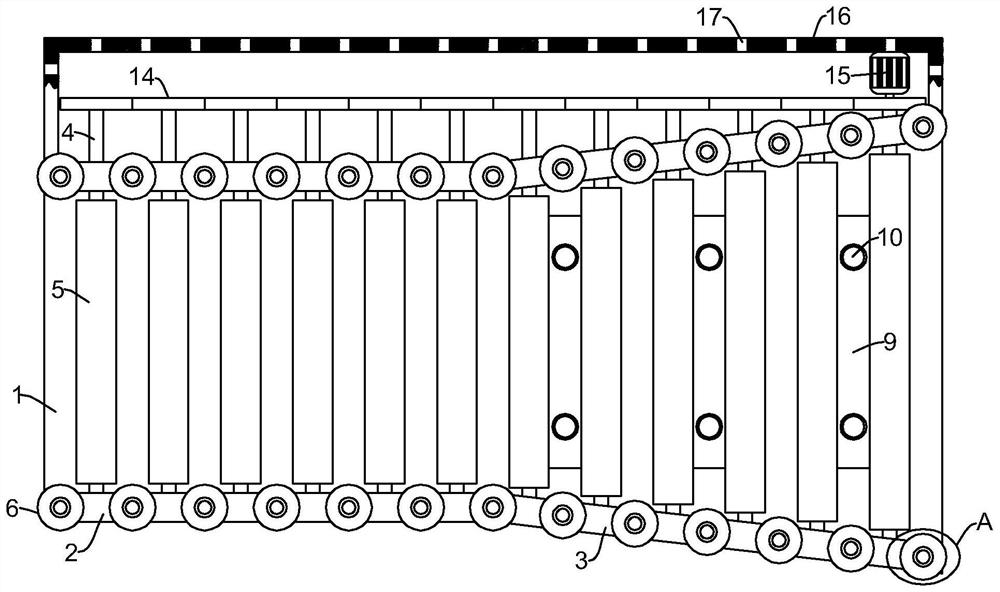
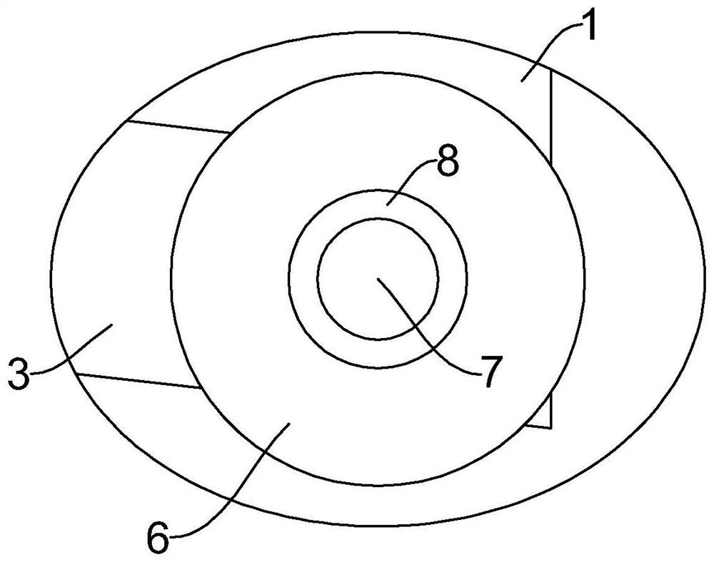
[0032] refer to Figure 1-4 , an intelligent deviation correction device for a compound rolling mill, comprising two first connecting plates 2, the two first connecting plates 2 are arranged parallel to each other, and a second connecting plate 3 is fixedly arranged on one end of the first connecting plate 2, and the second connecting plate 3 and the first connecting plate 2 are equidistant and run through the first rotating shaft 4, and the second connecting plate 3 and the first connecting plate 2 and the first rotating shaft 4 are jointly fixed with a second bearing 11, On the first rotating shaft 4 between the two second connecting plates 3 and the two first connecting plates 2, the first guide roller 5 is fixedly set with the center of the shaft, and the first connecting plate 2 and the second connecting plate 3 are connected together. The side is equally spaced and vertically fixedly provided with a second rotating shaft 7, the second rotating shaft 7 is coaxially sleeve...
Embodiment 2
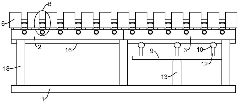
[0036] In Embodiment 1, although there is no need to perform multiple deviation correction operations, which reduces the labor intensity, when performing deviation correction on the first guide roller 5 between the two second connecting plates 3, it is still necessary to manually move the plate, although It is not necessary to lift the board completely, but under the joint action of the gravity of the board itself and the friction between the board and the first guide roller 5, the labor intensity is very small when correcting the deviation manually. figure 1 and 3 , as another preferred embodiment of the present invention, the difference from Embodiment 1 is that a moving plate 9 is jointly provided under a plurality of first guide rollers 5 between two second connecting plates 3, and the moving plate 9 is arranged on Between the first guide roller 5 and the base 1, the movable plate 9 and the first guide roller 5 are equidistantly and vertically fixedly provided with support...
Embodiment 3
[0039] In Embodiment 2, there is no power to drive the first guide roller 5 to rotate, and an additional thrust is required to push the plate to move on the first guide roller 5, and gears 14 are fixed on one end of the plurality of first rotating shafts 4 coaxially. , two adjacent gears 14 mesh with each other, one of the gears 14 is fixed with a rotating motor 15, the top of the output shaft of the rotating motor 15 is fixed on the gear 14 with the same axis, and the rotating motor 15 is fixed with a supporting and fixing mechanism , under the action of the supporting and fixing mechanism, the position of the rotating motor 15 is fixed, the rotating motor 15 drives the gear 14 to rotate, and the gear 14 drives the first rotating shaft 4 and the first guide roller 5 to rotate, and then can drive the first guide roller 5 The movement of the plates on the board.
[0040] The supporting and fixing mechanism includes a "匚"-shaped protective plate 16, and the two ends of the prote...
PUM
 Abstract
Description
Claims
Application Information
 - R&D Engineer
- R&D Manager
- IP Professional
- Industry Leading Data Capabilities
- Powerful AI technology
- Patent DNA Extraction
Browse by: Latest US Patents, China's latest patents, Technical Efficacy Thesaurus, Application Domain, Technology Topic, Popular Technical Reports.
© 2024 PatSnap. All rights reserved.Legal|Privacy policy|Modern Slavery Act Transparency Statement|Sitemap|About US| Contact US: help@patsnap.com