Stand column shaping device of fan stand column automatic machining equipment and technology thereof

A shaping device and automatic processing technology, applied in metal processing equipment, feeding device, positioning device, etc., can solve the problems of damage to the inner tube, the use of the outer tube and the inner tube that affect the column, and processing errors.

Inactive Publication Date: 2021-06-01
钟起官
View PDF0 Cites 0 Cited by
  • Summary
  • Abstract
  • Description
  • Claims
  • Application Information

AI Technical Summary

Problems solved by technology

[0003] However, when the existing fan column processing device is processing the outer tube and the inner tube of the column, the outer tube and the inner tube of the column are processed manually, including cutting the inner tube and the outer tube into required lengths. , and then transferred to the punching machine to punch the inner tube and the outer tube. Then, the inner tube and the outer tube need to be transferred to the punching machine for double buckle punching. After punching the double buckle, the inner circle of both ends of the inner tube And the outer circle is shaped on the shaping machine. The whole processing process needs to be transferred between multiple equipments. The investment in equipment takes up a lot of space, and the efficiency of manual processing is low and it is easy to cause processing errors during the processing process, which affects the appearance of the column. Subsequent use of tube and inner tube
[0004] In the process of shaping the inner tube, the existing device does not have a good shaping effect, which is likely to cause damage to the inner tube and affect the subsequent processing. Moreover, the shaping operation is performed manually, and the degree of automation is low.

Method used


Image

  • Stand column shaping device of fan stand column automatic machining equipment and technology thereof
  • Stand column shaping device of fan stand column automatic machining equipment and technology thereof
  • Stand column shaping device of fan stand column automatic machining equipment and technology thereof

Examples


Embodiment 1

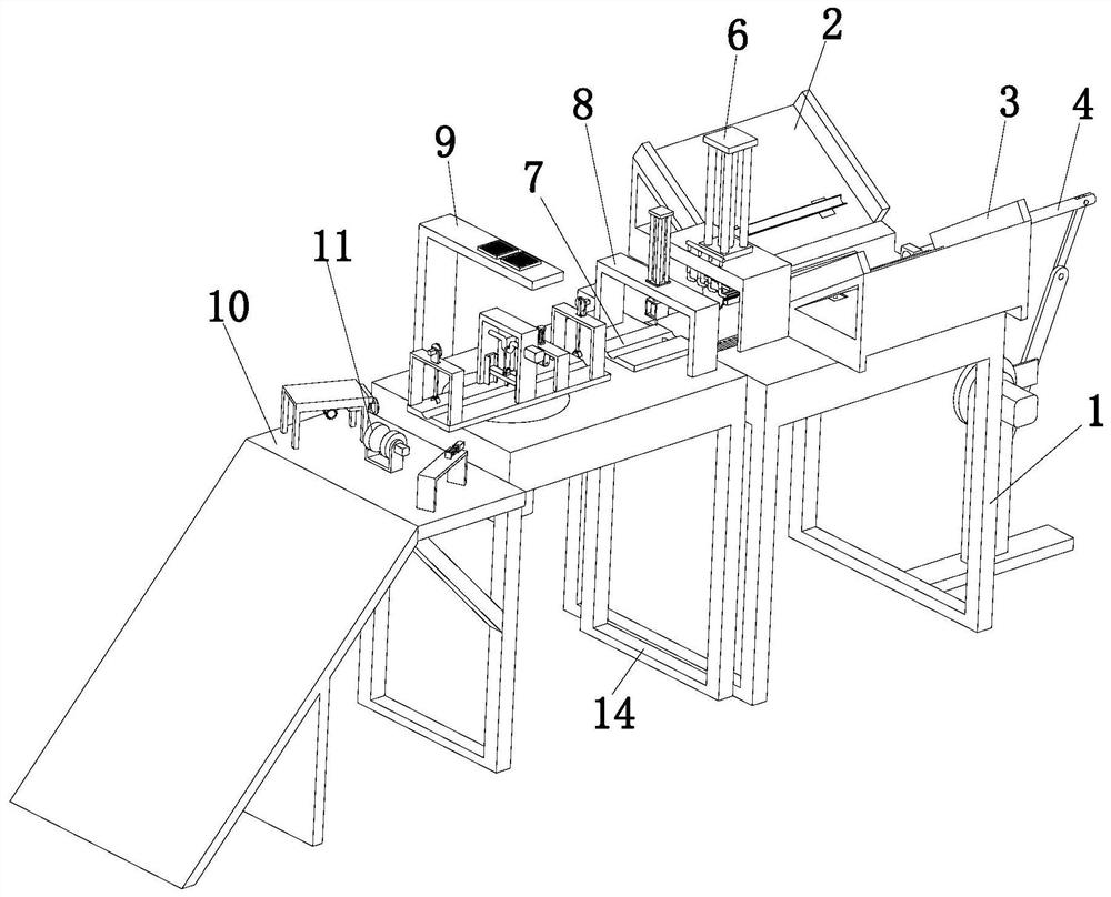
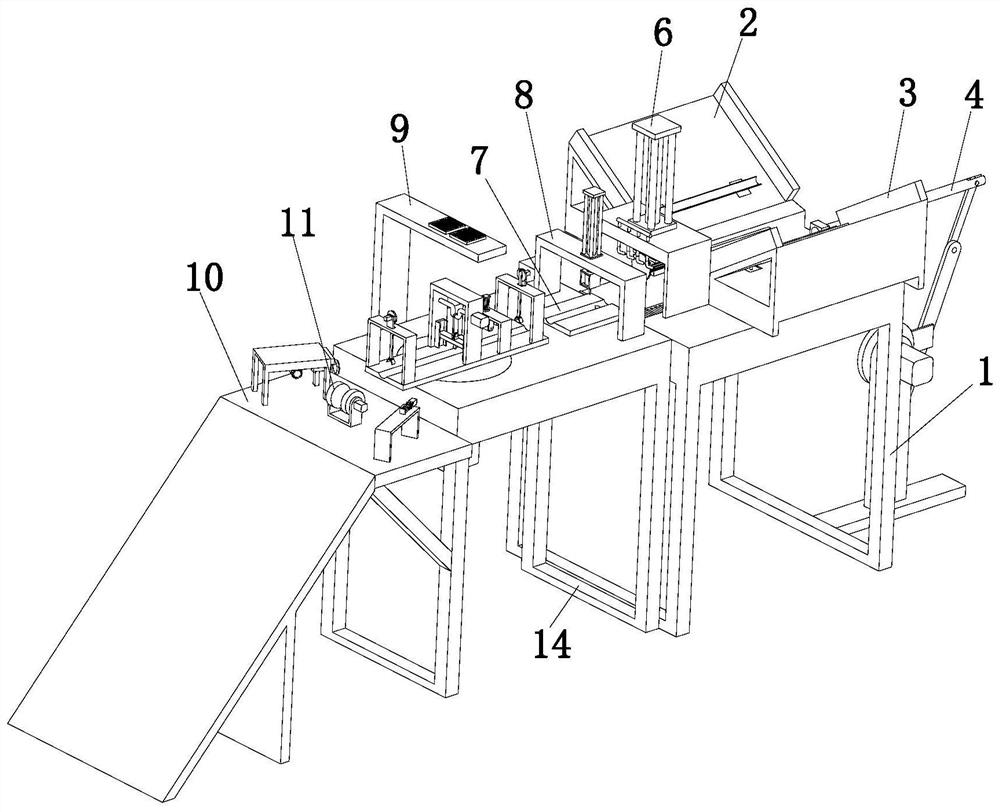
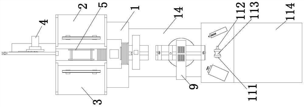
[0045] Combine below Figure 1 to Figure 15 As shown, the embodiment of the present invention provides an automatic processing equipment for a fan column, including a mounting frame 1, an outer tube column feeding device 2, an inner tube column feeding device 3, a column feeding moving device 4, a column fixing device 5, The column cutting device 6, the column moving device 7, the column punching device 8, the support frame 14, the column shaping device 9, the blanking fixing frame 10 and the column blanking device 11, the mounting frame 1 is arranged vertically, and the outer The tube column feeding device 2 and the inner tube column feeding device 3 are symmetrically arranged on the top of the mounting frame 1, the column feeding moving device 4 is arranged on the side of the mounting frame 1, and the column feeding moving device 4 and the mounting frame 1 are arranged. Sliding fit, the column fixing device 5 is arranged on the mounting frame 1 and the column fixing device 5...

Embodiment 2

[0066] The process of the column shaping device of the above-mentioned fan column automatic processing equipment comprises the following steps:

[0067]Step 1. Fix the two ends of the inner tube and the outer tube of the fan column: First, after moving the column to the column fixing plate 913, the drive motor 972 works to drive the drive plate 973 to rotate, and the drive plate 973 rotates to drive the drive plate 974. Moving up and down on the fixing frame 971, the driving plate 974 moves downward to drive the column circular plate 975 to move downward, and the two ends of the inner tube and the outer tube placed on the column fixing plate 913 are fixed to prevent the outer tube and the inner tube from being damaged. When the tube is punched and reshaped, the position of the inner tube and the outer tube is offset, which affects the processing of the inner tube and the outer tube;

[0068] Step 2. Double punch the inner tube and the outer tube: Then, when the inner tube and ...


PUM


Abstract

The invention discloses a stand column shaping device of fan stand column automatic machining equipment, and belongs to the technical field of fans. The device comprises a support frame, a stand column shaping device and a blanking fixing frame, wherein the stand column shaping device comprises a stand column rotating assembly, a stand column conveying assembly, a stand column stamping assembly, a dust cleaning assembly, a stand column inner circle spinning shaping assembly, a stand column outer circle spinning shaping assembly and two stand column two-side fixing assemblies. The stand column rotating assembly is arranged on the support frame, the two stand column two-side fixing assemblies are symmetrically arranged at two ends of the top of the stand column rotating assembly, the stand column conveying assembly is vertically arranged on the stand column rotating assembly, the stand column punching assembly is arranged on the stand column rotating assembly, the stand column inner circle spinning shaping assembly and the stand column outer circle spinning shaping assembly are symmetrically arranged on the side wall of the discharging fixing frame, and the dust cleaning assembly is arranged on the side wall of the support frame. The device can achieve automatic double-buckle punching and shaping operation on the inner pipe of the stand column.

Description

technical field [0001] The invention relates to the technical field of fans, in particular to a column shaping device of an automatic fan column processing equipment and a process thereof. Background technique [0002] The column fan is a fan using a centrifugal fan. It adopts a cylindrical column shape and does not take up space when placed in the room; and the fan blade is wrapped in the shell, which is difficult to touch and relatively safe; and the sound is relatively small, Quiet and no noise. Because of these advantages, it has been widely used. The fan column is generally composed of a column outer tube and a column inner tube. In actual use, the inner tube of the column is sleeved in the column inner tube. [0003] However, when processing the outer tube and inner tube of the column in the existing fan column processing device, the outer tube and inner tube of the column are manually processed, including cutting the inner tube and the outer tube into the required l...

Claims


Application Information

Patent Timeline
Patent Type & Authority Applications(China)
IPC IPC(8): B21D3/14B21D43/00B08B5/02B21D39/04B21D43/08
CPCB08B5/02B21D3/14B21D39/04B21D43/003B21D43/006B21D43/08
Inventor 钟起官
Owner 钟起官
Why Eureka
Try Eureka