Electric car coupler pushing device, car couplers and working method of electric car coupler pushing device

A technology of electric coupler and push device, which is applied in the direction of transportation and packaging, railway car body parts, railway vehicle coupling accessories, etc. It can solve the problems of accurate coupling and automatic coupling of couplers, etc., to increase the distance and realize The effect of precise linkage

Active Publication Date: 2021-06-01
CRRC QINGDAO SIFANG ROLLING STOCK RES INST +1
View PDF9 Cites 3 Cited by
  • Summary
  • Abstract
  • Description
  • Claims
  • Application Information

AI Technical Summary

Problems solved by technology

[0005] The purpose of the present invention is to provide a pushing device for an electric coupler to solve the technical problem in the prior art that the automatic coupling coupler with a short guide length cannot be accurately coupled through mechanical driving

Method used


Image

  • Electric car coupler pushing device, car couplers and working method of electric car coupler pushing device
  • Electric car coupler pushing device, car couplers and working method of electric car coupler pushing device
  • Electric car coupler pushing device, car couplers and working method of electric car coupler pushing device

Examples


Embodiment Construction

[0073] In the following, the present invention will be specifically described through exemplary embodiments. It should be understood, however, that elements, structures and characteristics of one embodiment may be beneficially incorporated in other embodiments without further recitation.

[0074] In the description of the present invention, it should be noted that the terms "inner", "outer", "upper", "lower", "front", "rear", "first", "second", "third", "fourth" The orientation or positional relationship indicated by etc. is based on the positional relationship shown in the drawings, and is only for the convenience of describing the present invention and simplifying the description, rather than indicating or implying that the referred device or element must have a specific orientation or be constructed in a specific orientation. and operation, and therefore should not be construed as limiting the invention.

[0075] In the description of the present invention, "installation",...


PUM


Abstract

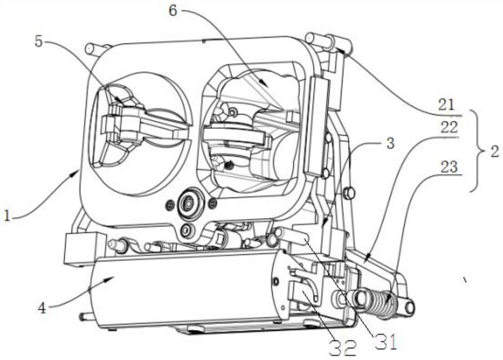
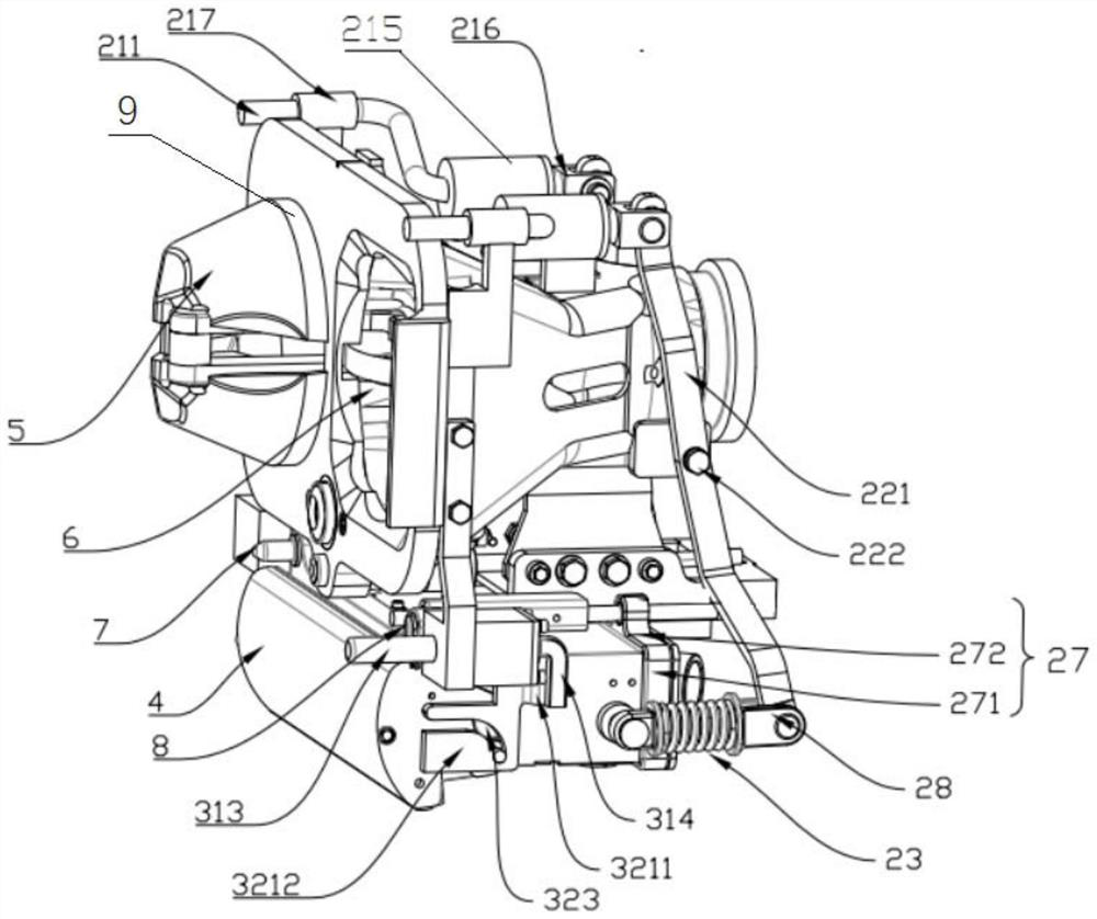
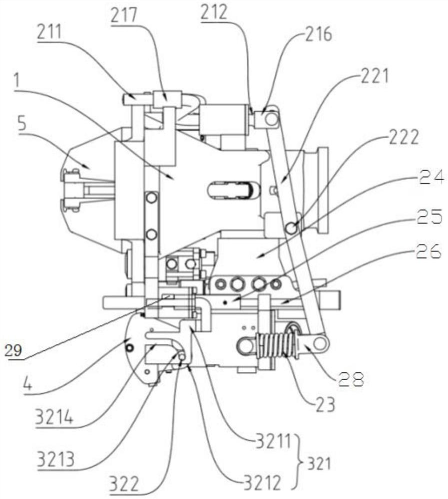
The invention discloses an electric car coupler pushing device, car couplers and a working method of the electric car coupler pushing device. The electric car coupler pushing device comprises push trigger mechanisms, and one end of each push trigger mechanism extends towards the opposite car coupler; when car couplers are automatically coupled, the car couplers on the opposite side can push the push trigger mechanisms to move synchronously; the device further comprises a pushing mechanism which is arranged on an electrical car coupler, and a transmission mechanism, one end of the transmission mechanism is connected with the push trigger mechanisms, and the other end of the transmission mechanism is connected with the pushing mechanism. When the car couplers are automatically coupled, the push trigger mechanisms drive the transmission mechanism to move under the pushing action of the car couplers on the opposite side, and the transmission mechanism pushes the pushing mechanism to push out the electrical car coupler. The technical problem that in the prior art, an automatic coupling car coupler with the short guiding length cannot achieve accurate coupling of the electrical car coupler through mechanical driving is solved.

Description

technical field [0001] The invention belongs to the technical field of rail vehicle couplers, and in particular relates to an electric coupler pushing device, a coupler and a working method thereof. Background technique [0002] The automatic coupler is one of the important parts of the vehicle, which mainly includes mechanical couplers and electrical couplers. Among them, the electric coupler is divided into pneumatic, electric and mechanical drive according to the drive type. Compared with the pneumatic and electric drive types, the mechanical drive mainly uses the thrust when the coupler is connected as the driving force. The trailer coupler has a simple structure, low operation and maintenance costs, and effectively saves space. [0003] In order to ensure the accurate connection of the electric coupler, the cooperation between the secondary positioning pin and the positioning sleeve of the electric coupler is generally used to ensure the precise cooperation of the int...

Claims


Application Information

Patent Timeline
Patent Type & Authority Applications(China)
IPC IPC(8): B61G7/00
CPCB61G7/00
Inventor 刘佺杜锦涛陆青松宋波徐晓晨王泽理庄晓龙
Owner CRRC QINGDAO SIFANG ROLLING STOCK RES INST
Why Eureka
Try Eureka