
Bicycle rope transmission mechanism

A rope transmission and bicycle technology, which is applied to vehicle parts, vehicle gearboxes, rider drives, etc., can solve the problems of wide range of motion of the knee joint, swelling and discomfort of the knee joint, low transmission efficiency, etc., and is easy to promote on a large scale , long service life and smooth power transmission

Inactive Publication Date: 2021-06-01
辛永升
View PDF0 Cites 1 Cited by
  • Summary
  • Abstract
  • Description
  • Claims
  • Application Information

AI Technical Summary

Problems solved by technology

[0003] Existing bicycles are driven by the feet during riding, and the crank rotates in circles. The torque goes from zero to maximum and then to zero again and again. In addition, the transmission efficiency of the chain drive is slightly low, and the cyclist will consume more physical strength for long-distance riding, resulting in the comfort range of ordinary people riding an ordinary non-variable bicycle can only be within a short distance of two to three kilometers. The range is large, and people with slightly better physical strength will feel soreness and discomfort in the knee joints after about ten kilometers. It is difficult for ordinary people to ride long distances.

Method used


Image

  • Bicycle rope transmission mechanism
  • Bicycle rope transmission mechanism
  • Bicycle rope transmission mechanism

Examples


Embodiment Construction

[0020] In order to make the purpose, technical solution and advantages of the present invention clearer, the present invention will be further described in detail below through specific implementation examples and in conjunction with the accompanying drawings.

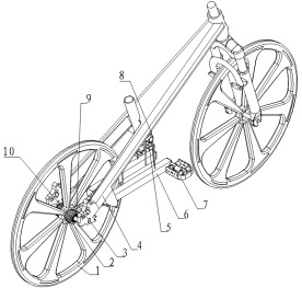
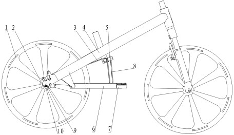
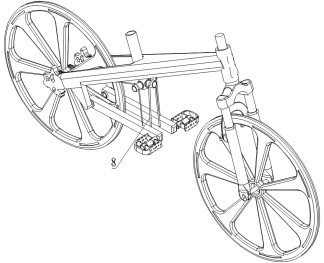
[0021] see figure 1 , the invention discloses a bicycle rope transmission mechanism, comprising a double ratchet rear wheel 1, a flywheel 2, a transmission rope 3, a frame 4, a fixed pulley 5, a connecting rod 6, a pedal 7, a linkage rope 8, a rear wheel shaft 9 and Scroll spring 10; two flywheels are installed on both sides of the double ratchet rear wheel, and then link to each other with the drive rope respectively. One end of the transmission rope is fixed on the flywheel and wound several times on the flywheel, then goes around the fixed pulley installed on the frame, and finally connects with corresponding connecting rods respectively. In consideration of actual needs and cost reduction, the rear wheel shaft can...


PUM


Abstract

The invention provides a bicycle rope transmission mechanism. The bicycle rope transmission mechanism comprises a double-ratchet-wheel rear wheel, flywheels, a transmission rope, a rack, fixed pulleys, a connecting rods, pedals, a linkage rope, a rear wheel shaft and a volute spiral spring. The two flywheels are installed on the two sides of the double-ratchet-wheel rear wheel, and one end of the transmission rope is fixed to the flywheels, wound on the flywheels for a plurality of circles, then wound around the fixed pulleys installed on the rack and connected with the corresponding connecting rods. A connecting rod mounting shaft can be independently mounted on the rack, and the rear wheel shaft can also be used. The front ends of the two connecting rods are wound around the fixed pulleys installed on the rack through the linkage rope to be connected together, and pedal linkage is guaranteed. One end of the spiral spring is installed on the rear wheel shaft, and the other end is installed on the flywheels to achieve winding recovery of the transmission rope. Circumferential motion is replaced by up-down reciprocating motion during riding, work can be done by means of the gravity of a human body, the force exerting function of the human body structure is exerted to the maximum extent, the comfort of a rider is improved, the number of parts is small, machining and maintenance are easy, and large-scale popularization is easy.

Description

technical field [0001] The invention belongs to the field of bicycle transmission and is a novel bicycle transmission mechanism. Background technique [0002] The transmission system of existing bicycles mostly uses chain transmission, and maintenance measures such as lubricating oil are often required. The chain is near the trousers, and the trousers are often stained with oil. After a long period of use, the chain will drop, unlink, and skip teeth. , If the chain is dropped and installed, it will also cause oily hands. The chain sprockets of general quality will be replaced in a short period of time due to wear. [0003] Existing bicycles are driven by the feet during riding, and the crank rotates in circles. The torque goes from zero to maximum and then to zero again and again. In addition, the transmission efficiency of the chain drive is slightly low, and the cyclist will consume more physical strength for long-distance riding, resulting in the comfort range of ordinar...

Claims


Application Information

Patent Timeline
Patent Type & Authority Applications(China)
IPC IPC(8): B62M23/00B62M1/24
CPCB62M1/24B62M23/00
Inventor 辛永升
Owner 辛永升
Learn More