Quickly-assembled steel reinforcement framework assembly in steel structure building exterior wall cladding

A technology for building exterior walls and steel skeletons, applied in building components, building reinforcements, buildings, etc., can solve the problems of wasting time and inconvenient disassembly and maintenance of steel skeletons, and achieve the effects of improving stability, rapid disassembly, and rapid disassembly and maintenance.

Active Publication Date: 2021-06-01
周阳
View PDF6 Cites 0 Cited by
  • Summary
  • Abstract
  • Description
  • Claims
  • Application Information

AI Technical Summary

Problems solved by technology

[0003] At present, many steel skeletons are welded on site. This method not only wastes time,

Method used


Image

  • Quickly-assembled steel reinforcement framework assembly in steel structure building exterior wall cladding
  • Quickly-assembled steel reinforcement framework assembly in steel structure building exterior wall cladding
  • Quickly-assembled steel reinforcement framework assembly in steel structure building exterior wall cladding

Examples


Embodiment 1

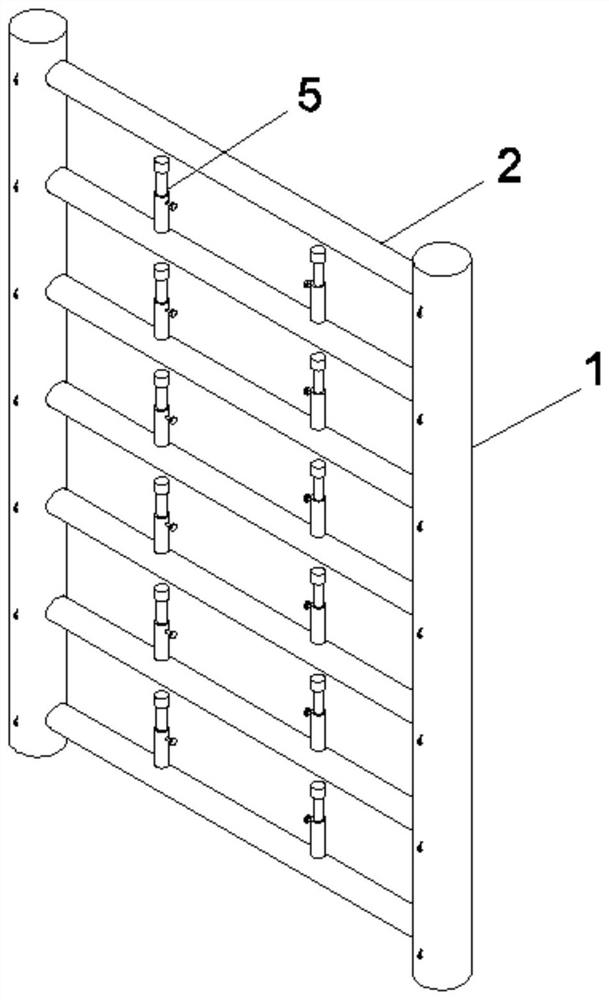
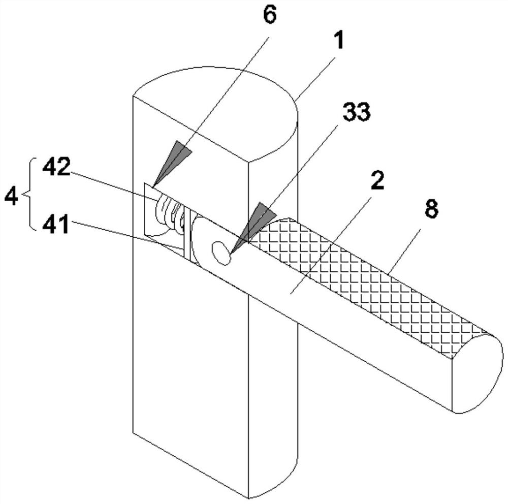
[0034]Such asFigure 1-4 As shown, the steel skeleton assembly in the outer wall of the steel structure building exterior wall is: first steel frame 1, second steel frame 2, pull mechanism 9, push mechanism 4 and support mechanism 5, first steel frame 1 The sidewall is opened on the side wall, and the second steel frame 2 is mounted on the side wall of the first steel frame 1 by the fixing mechanism 3, and the fixing mechanism 3 includes a fixing rod 31, a first spring 32, and a fixed hole. 33. The inside of the first steel frame 1 is opened with a slide 7 in communication with the fixed groove 6, and the fixing lever 31 is slidably coupled to the inside of the chute 7, and one end of the first spring 32 is located inside the chute 7 in the chute 7. One end is fixed, the other end of the first spring 32 is fixed to the inner wall of the chute 7, and the second steel frame 2 is opened to the sidewall of the second steel frame 2 having a fixing hole 33 mounted with the fixing lever 31....

Embodiment 2

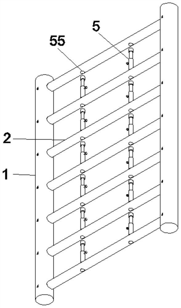
[0042]Such asFigure 5-9As shown, in order to further improve the assembly efficiency of the steel skeleton assembly, the support mechanism 5 unified standards are pre-installed in a reasonable position of the second steel frame 2, such as the welding or threaded connection, because the support mechanism 5 is pre-installed in the first On the two-steel frame 2, it is not necessary to remove it in the disassembly of the reinforced frame assembly. This embodiment does not repeatedly describe its specific installation mode, and no longer considers the pre-installed time problem, which is intended to solve the specific use of specific use. The problem of disassembly and assembly of the steel branches, in this embodiment, the support mechanism 5 specifically includes a support barrel 51, a support rod 52, a pinch device 53, and a wire block 55 is fixed under the support barrel 51, and the iron block 55 and the supportor. The interior of the 51 terminal constitutes the card slot 56, the ir...


PUM


Abstract

The invention provides a quickly-assembled steel reinforcement framework assembly in a steel structure building exterior wall cladding. The quickly-assembled steel reinforcement framework assembly in the steel structure building exterior wall cladding comprises a first steel frame, a second steel frame, a pulling mechanism, a pushing mechanism and a supporting mechanism, a fixing rod is slidably connected to the interior of a sliding groove, one end of a first spring is fixedly connected with the end, located inside the sliding groove, of the fixing rod, the other end of the first spring is fixedly connected with the inner wall of the sliding groove, a fixing hole matched with the fixing rod is formed in the side wall, close to the edge, of the second steel frame, the pulling mechanism is installed on the side wall of the first steel frame, the pushing mechanism is installed inside the fixing groove, and the supporting mechanism is installed at the top of the second steel frame. The quickly-assembled steel reinforcement framework assembly in the steel structure building exterior wall cladding has the advantages that a steel reinforcement framework can be rapidly installed, time can be saved, and the steel reinforcement framework assembly can be rapidly disassembled and is convenient to maintain.

Description

Technical field[0001]The present invention relates to the technical field of building materials, and more particularly to a steel skeleton assembly in a rapidly assembled steel structural building exterior wall hanging plate.Background technique[0002]The outer wall hanging board is a type of building material. It is a building sheet for the exterior wall. It is the outer surface of the wall by drying and other construction methods to achieve decorative or insulation. Inside the external wall scraper Support for steel skeletons.[0003]At present, many steel skeletons are soldering on-site, which is not only wasting time, but also is very inconvenient when needed for removing the steel skeleton.[0004]Therefore, it is necessary to provide a rapidly assembled steel structural building exterior wall hanging plate with steel backbone assembly to solve the above technical problems.Inventive content[0005]The technical problem solved by the present invention is to provide a rapid installation...

Claims


Application Information

Patent Timeline
IPC IPC(8): E04C5/06
CPCE04C5/06E04C5/0636
Inventor 周阳张建华张振赵红鹤任丽芳王银丽代江燕何金华史特功梁创
Owner 周阳
Why Eureka
Try Eureka