Supercharge Your Innovation With Domain-Expert AI Agents!

Fixing device for narrow space

A fixing device and space technology, applied in the direction of mechanical equipment, connecting components, etc., can solve the problems of not being able to solve the problem of workpiece fixing well, the material of the workpiece does not meet the requirements, and the magnet adsorption and positioning are limited.

Active Publication Date: 2021-06-01
YUXIN TECH HUIZHOU
View PDF5 Cites 0 Cited by
  • Summary
  • Abstract
  • Description
  • Claims
  • Application Information

AI Technical Summary

Problems solved by technology

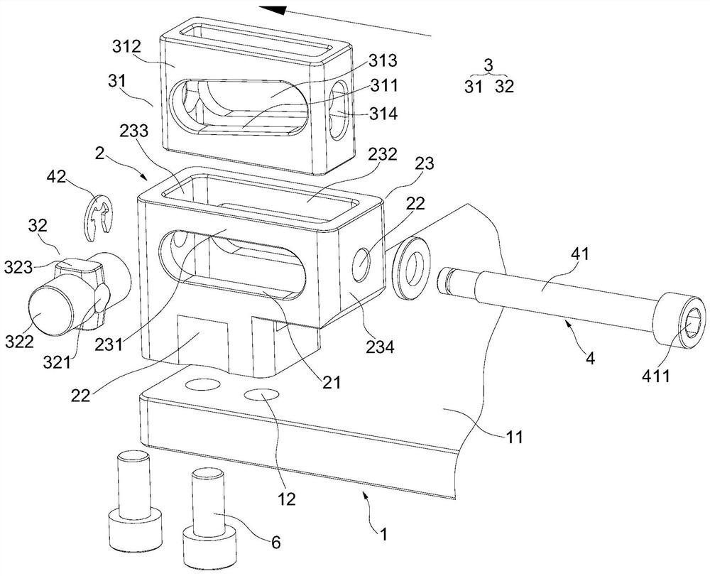
[0003] However, in production and manufacturing, there are some workpieces or parts that need to be fixed in a narrow space. If the space for the connection and fixing direction is just located on the narrow side of the narrow space, and there is not enough space for work, then the general connection and fixation method is used. The structure is difficult to complete the installation and fixation
In this regard, some solutions have appeared, such as magnetic adsorption positioning or wedge positioning, but the magnetic adsorption positioning is limited by the material, and a large part of the workpiece material does not meet the requirements; and the wedge positioning program is in It is difficult to remove when disassembled, and some other fixing solutions require special tools to complete the installation
None of these solutions can well solve the problem of fixing workpieces in narrow spaces

Method used


Image

  • Fixing device for narrow space
  • Fixing device for narrow space
  • Fixing device for narrow space

Examples


Embodiment Construction

[0030] Below, the present invention will be further described in conjunction with the accompanying drawings and specific implementation methods. It should be noted that, under the premise of not conflicting, the various embodiments described below or the technical features can be combined arbitrarily to form new embodiments. .

[0031] In the description of this application, it is to be understood that the terms "center", "upper", "lower", "front", "rear", "left", "right", "vertical", "horizontal", The orientation or positional relationship indicated by "top", "bottom", "inner", "outer", etc. is based on the orientation or positional relationship shown in the drawings, and the orientation "front" has been shown by arrows in the figure, just for the purpose of It is convenient to describe the application and simplify the description, but not to indicate or imply that the device or element referred to must have a specific orientation, be constructed and operate in a specific ori...


PUM


Abstract

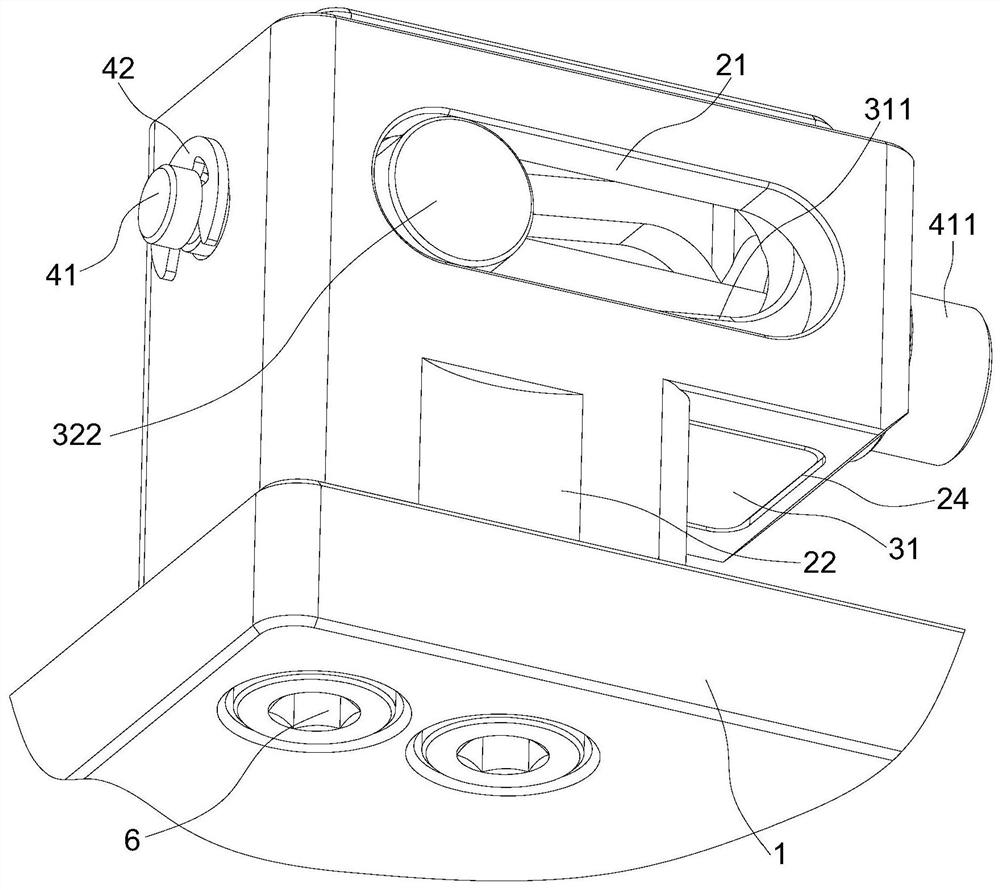
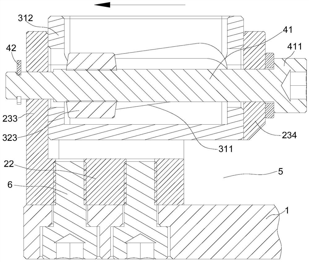
The invention discloses a fixing device for a narrow space. The fixing device comprises a supporting seat, a connecting seat and a movable assembly. The supporting seat comprises a supporting face. The connecting seat is provided with sliding rails and external holes. The movable assembly is provided with a pressing piece and sliding pieces, the pressing piece is provided with an inclined face facing the sliding pieces, and a pressing space is formed between the lower surface of the pressing piece and the supporting face. The sliding pieces are connected with the sliding rails in a slidable mode, an internal thread hole with an internal thread is formed in each sliding piece, and the sliding pieces are pressed on the inclined face. A rotating rod is connected to the external connection holes in a rotatable mode and is screwed with the internal threaded holes. When the rotating rod is rotated, the sliding pieces can slide along the sliding rails, the sliding pieces are pressed on different parts of the inclined face, and then the pressing piece is driven to slide up and down along a containing groove so that the height of the pressing space can be increased or decreased. The fixing device for the narrow space can be assembled and disassembled in the direction perpendicular to the connecting and fixing direction, and the difficulty that fixing and operation are difficult due to insufficient space in the connecting and fixing direction is overcome.

Description

technical field [0001] The invention relates to the technical field of fixing structures, in particular to a fixing device used in narrow spaces. Background technique [0002] The connection and fixation between workpieces or parts is very common in daily production and life. The more commonly used connection and fixing structures include bolt structures, compression or clamping structures, etc., but such structures generally need to be in the same direction as the connection and fixing direction. For fixing operation, in general, when there is enough space to connect the fixing direction, it is convenient to use tools such as screwdrivers for fixing operation. [0003] However, in production and manufacturing, there are some workpieces or parts that need to be fixed in a narrow space. If the space for the connection and fixing direction is just located on the narrow side of the narrow space, and there is not enough space for work, then the general connection and fixation me...

Claims


Application Information

Patent Timeline
IPC IPC(8): F16B21/12
CPCF16B21/12
Inventor 钟健英杨同坤王良基吴衍
Owner YUXIN TECH HUIZHOU
Features
  • R&D
  • Intellectual Property
  • Life Sciences
  • Materials
  • Tech Scout
  • Unparalleled Data Quality
  • Higher Quality Content
  • 60% Fewer Hallucinations
Learn More