A splicing led lamp

A technology of LED lamps and LED light sources, applied in the field of lighting, can solve problems such as electric shock hazards and complicated operations, and achieve the effect of ensuring safety and fast and simple electrical connection

Active Publication Date: 2022-06-28
XIAMEN GUANGPU ELECTRONICS
View PDF15 Cites 0 Cited by
  • Summary
  • Abstract
  • Description
  • Claims
  • Application Information

AI Technical Summary

Problems solved by technology

The disadvantage is that when splicing, the mask of each lamp unit must be opened, and the slots must be fully opened before the connector can be installed. It is equivalent to dismantling the lamp unit at the installation site, which is complicated and has potential for electric shock

Method used


Image

  • A splicing led lamp
  • A splicing led lamp
  • A splicing led lamp

Examples


Embodiment 1

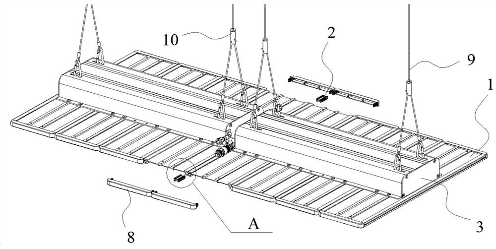
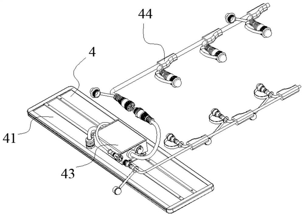
[0033] like Figures 1 to 7 As shown, a splicing type LED lamp is provided with a lamp module 1 and a connector 2. The lamp module 1 is provided with a power supply box 3 and a lamp unit 4. The lamp unit 4 is provided with a radiator 41 and an LED light source. 42. Driving unit 43, the LED light source 42 is arranged on the lower surface of the radiator 41, the driving unit 43 is arranged on the upper surface of the radiator 41, and the left and right sides of the radiator 41 are provided with The C-shaped through-hole slot 5 runs through the front and rear surfaces of the radiator 41, the upper surface of the radiator 41 is also provided with screw holes, the lamp module 1 is provided with four lamp units 4, and the power box 3 is covered in On the driving unit 43 , the power box 3 is locked on the screw holes by screws, and the power box 3 is provided with input and output lines 44 , and the driving units of the four lighting units 4 in the lighting module 1 43 are connecte...

Embodiment 2

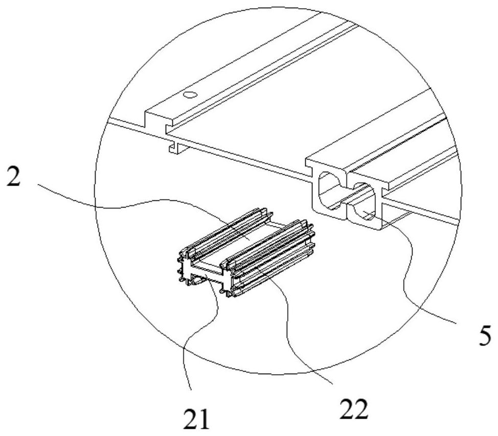
[0042] like Figures 8 to 9 As shown in the figure, the splicing type LED lamp is composed of lamp modules 1 connected and spliced ​​in parallel, and the end faces of the two adjacent lamp modules 1C-type through-hole grooves 5 are aligned and tightly attached. Each of the columnar parts 22 has a part disposed in the two C-shaped through-hole grooves 5 whose end faces are aligned.

[0043] The rest are the same as the first embodiment.

Embodiment 3

[0045] like Figure 10 As shown, the spliced ​​LED lamp is composed of lamp modules 1 spliced ​​together, the connector 2 is provided with a first connector 21 and a second connector 22, and the two columnar parts 22 of the first connector 2 are A part of each is disposed in the two C-shaped through-hole slots 5 aligned with the end faces of the two adjacent lamp modules 1, and the two columnar parts 22 of the second connector 2 are respectively disposed in the adjacent two. The lamp module 1 is in two C-shaped through-hole grooves 5 that are closely attached side to side.

[0046] The rest are the same as the first embodiment.


PUM


Abstract

The invention relates to a splicing LED lamp, which is provided with a lamp module and a connector. The lamp module is provided with a power supply box and a lamp unit. The lamp unit is provided with a radiator, an LED light source, a drive unit, and a connecting wire. The LED light source is arranged on the lower surface of the radiator, the drive unit is arranged on the upper surface of the radiator, and the left and right sides of the radiator are provided with C-shaped through-hole grooves that run through the front and rear surfaces of the radiator , the driving units of several lamp units in the lamp module are connected through input and output lines, the connector is provided with a flat plate and a columnar portion, and the two columnar portions are symmetrically arranged at both ends of the flat plate Part, the splicing LED lamp is composed of several lamp modules spliced ​​together, and the adjacent lamp modules are connected by connectors.

Description

technical field [0001] The invention belongs to the field of lighting, and in particular relates to a splicing type LED lamp. Background technique [0002] LED is a new type of energy-saving, environmentally friendly, long-life light source. LED lighting products have been widely used in the field of general lighting, and have achieved significant energy saving and emission reduction effects. With the continuous development of technology, the application field of LED lighting continues to expand. For example, with the advantages of LED light-emitting bandwidth and wavelength selection, LED lighting fixtures have become the preferred light source for plant factories. However, the size and lighting spectrum of lamps in plant factories need to be flexibly adjusted according to specific plant species, which requires that LED lamps must be able to be disassembled and spliced. [0003] Chinese patent CN201921244802.1 discloses a module splicing floodlight, by connecting 4 LED f...

Claims


Application Information

Patent Timeline
Patent Type & Authority Patents(China)
IPC IPC(8): F21S8/06F21V21/00F21V23/00F21V23/06F21V15/01F21Y115/10
CPCF21S8/061F21V21/00F21V23/003F21V23/06F21V15/01F21Y2115/10
Inventor 苏海鼎陈世福沈谦筑
Owner XIAMEN GUANGPU ELECTRONICS
Why Eureka
Try Eureka