A ground rail type automatic wire rope take-up machine without lifting device

A lifting device and wire rope technology, applied in the field of mechanical devices, can solve problems such as low work efficiency, complex structure, and affecting the clamping hole of the rope reel, and achieve the effects of simplifying the overall structure, overcoming easy deformation, and compact structure

Inactive Publication Date: 2017-06-23
UNIV OF JINAN
View PDF7 Cites 0 Cited by
  • Summary
  • Abstract
  • Description
  • Claims
  • Application Information

AI Technical Summary

Problems solved by technology

The traditional spiral lifting device often affects the centering of the rope reel clamping hole due to the inaccurate lifting position of the rope reel clamping shaft, the work efficiency is low, and the structure is more complicated

Method used


Image

  • A ground rail type automatic wire rope take-up machine without lifting device
  • A ground rail type automatic wire rope take-up machine without lifting device
  • A ground rail type automatic wire rope take-up machine without lifting device

Examples


Embodiment Construction

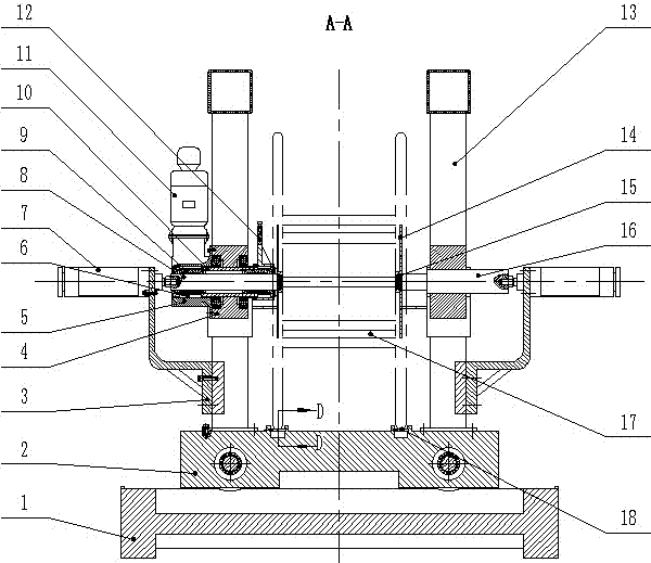
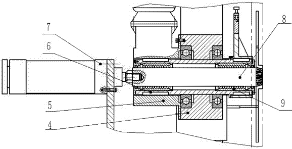
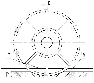
[0020] Below in conjunction with the accompanying drawings, the specific implementation of the present invention will be further introduced: as shown in the figure, a ground rail type automatic wire take-up machine without a lifting device, including: a rope reel clamping device, the rope reel clamping device Including support frame 3, flat key 6, hydraulic cylinder 7, active thimble shaft 8, linear bearing 9, drive shaft outer shaft 10, column 13, roller 15, passive thimble shaft 16; rope reel winding device, the rope reel The winding device includes a fixed plate 4, a motor support plate 5, a linear bearing 9, a drive shaft outer shaft 10, a motor with a reducer 11, a dial 12, a cross chuck 14, a roller 15, a rope reel 17, and a shaft frame 21; Wiring device, described wiring device comprises ground rail 1, base 2, roller 19, drive shaft 20, planetary cycloid pinwheel reducer, small sprocket 23, large sprocket 24; Guide rail device, described guide rail device comprises groun...


PUM


Abstract

The invention discloses an automatic ground rail type steel wire rope winding machine without a lifting device. The automatic ground rail type steel wire rope winding machine comprises a guide rail device, a rope coil clamping device, a rope coil winding device and a wiring device. According to the automatic ground rail type steel wire rope winding machine disclosed by the invention, a lifting mechanism in a traditional wire winding machine is replaced by mainly utilizing the guide rail device of which a bottom plate can be pulled out, a space is reserved for the rotation of a rope coil by pulling out the bottom plate after the rope coil is clamped, the convenience of disassembling the rope coil and the steel wire rope winding without a lifting mechanism are realized, and the problems that the lifting position of a rope coil clamping shaft is inaccurate and the centering efficiency and the working efficiency of a rope coil clamping hole are low are solved; a hydraulic cylinder symmetrically pushes a driving ejector pin shaft and a driven ejector pin shaft to move transversely in the axial direction, a force application point and a pressing point of the hydraulic cylinder are positioned in the same axis, the clamping and the winding of the rope coil are realized through a design that an inner shaft and an outer shaft are arranged in a nesting and isolating way and a series of rolling posts which are uniformly arranged at a clamping cone end along the circumferential direction, the problem that a whole framework is easy to deform is solved, the structure is compact, and safety and reliability are realized.

Description

technical field [0001] The invention relates to the field of mechanical devices, in particular to a ground rail type automatic wire rope take-up machine without a lifting device. Background technique [0002] As a wire rope take-up equipment, the wire take-up machine generally consists of a power device, a lifting device, a rope reel clamping device, a wiring and a winding device, etc. Most of the existing floor rail take-up machines are of gantry structure. The clamping force of the rope reel is located at the upper beam of the inner and outer shaft sleeve structure, and the pressing point is located at about 1 / 2 of the height of the gantry. This clamping method is easy The deformation of the overall structure is generated, and the winding of the steel wire rope is mostly carried out by lifting the rope reel with the lifting device, and the structure is relatively complicated. [0003] The force application point and the compression point of the rope reel clamping device o...

Claims


Application Information

Patent Timeline
Patent Type & Authority Patents(China)
IPC IPC(8): B65H54/553
Inventor 王慧赵霞崔卫华付超唐陆孙令东
Owner UNIV OF JINAN
Why Eureka
Try Eureka