Road surface flatness measuring device

A technology for measuring devices and road surfaces, which is applied in the directions of measuring devices, roads, roads, etc., can solve the problems of vibration of the measuring device, affecting the measurement accuracy, and reducing the detection accuracy of the measuring instrument.

Active Publication Date: 2021-06-01
杭州市城乡建设设计院股份有限公司
View PDF6 Cites 4 Cited by
  • Summary
  • Abstract
  • Description
  • Claims
  • Application Information

AI Technical Summary

Problems solved by technology

[0005] Aiming at the deficiencies of the prior art, the present invention provides a road surface smoothness measurement device, which has the detection speed block, and the measurement device is not easy to shake when being dragged by a vehicle, and the measured road surface can be cleaned during the measurement process, etc. , to solve the problem that when the vehicle...

Method used


Image

  • Road surface flatness measuring device
  • Road surface flatness measuring device
  • Road surface flatness measuring device

Examples


Embodiment 1

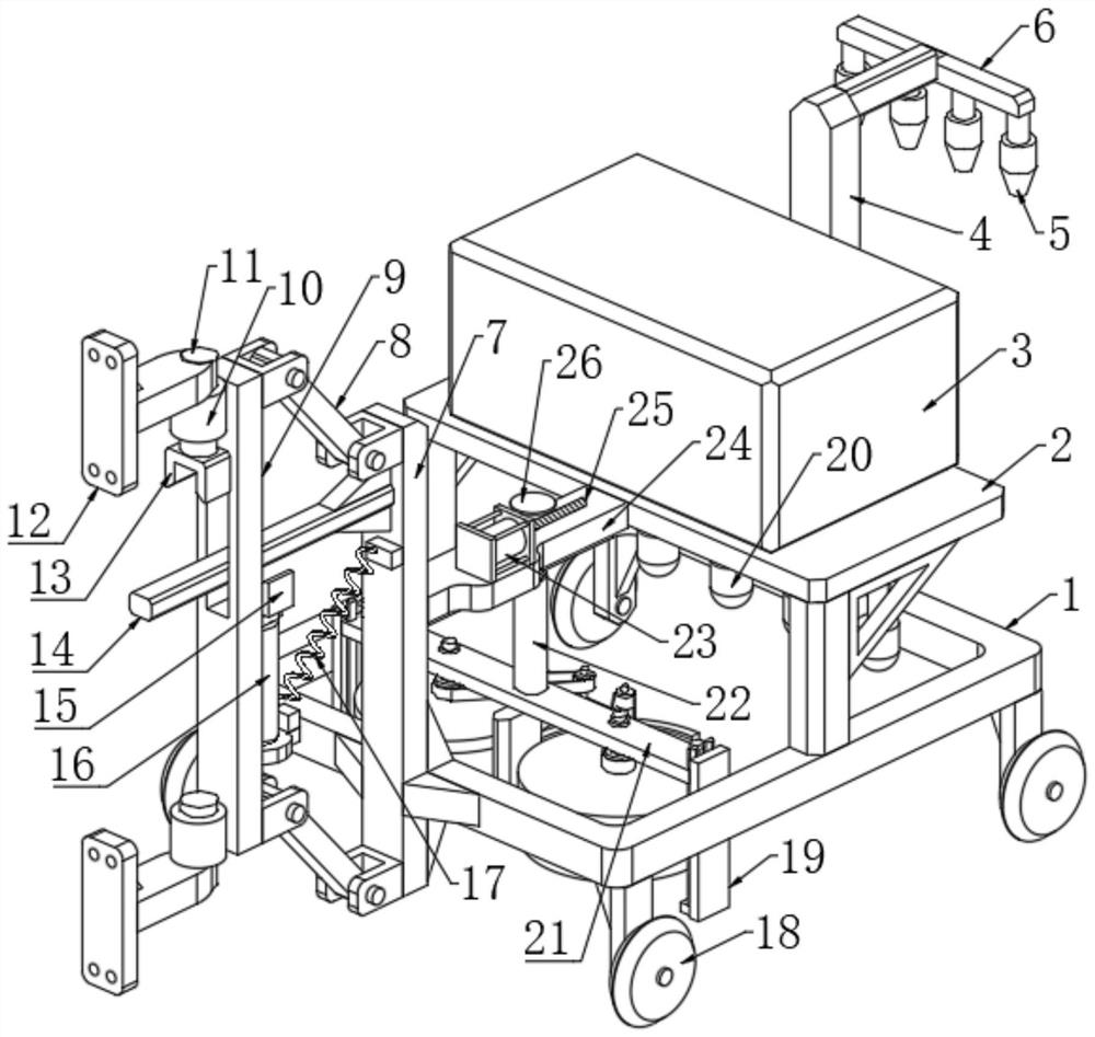
[0028] A road surface smoothness measurement device, comprising a detection host 3, a plurality of infrared sensors 5, a plurality of displacement sensors 20 and a rectangular frame 1, two vertical poles are fixedly connected to the upper edge of the rectangular frame 1, and the two vertical poles The upper end of the horizontal plate 2 is fixedly connected with the horizontal plate 2, the upper end of the horizontal plate 2 is fixedly connected with the lower end of the detection host 3, the lower end of the horizontal plate 2 is fixedly connected with a plurality of displacement sensors 20, and the center of the upper rear edge of the rectangular frame 1 is fixedly connected There is a support rod 4, the upper side of the rear end of the support rod 4 is fixedly connected with a fixed frame 6, the side wall of the fixed frame 6 is fixedly connected with a plurality of infrared sensors 5, and the inner side of the rectangular frame 1 is symmetrically fixedly connected with two ...

Embodiment 2

[0030] Embodiment 2: the difference based on Embodiment 1 is;

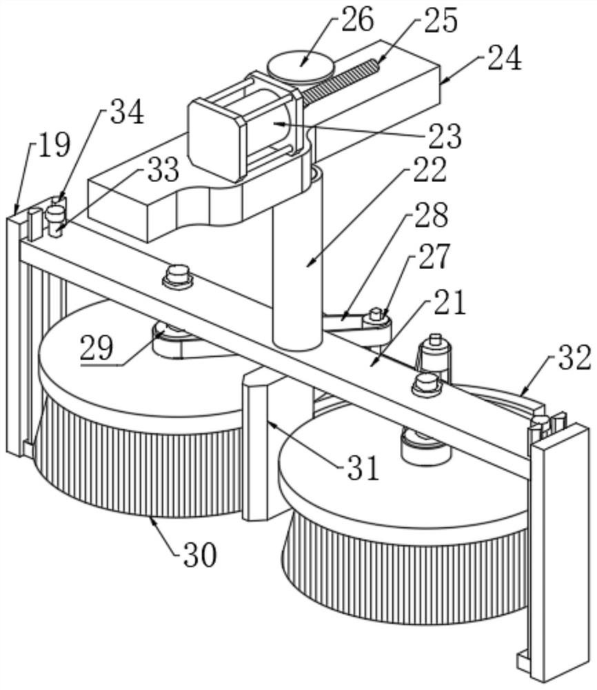
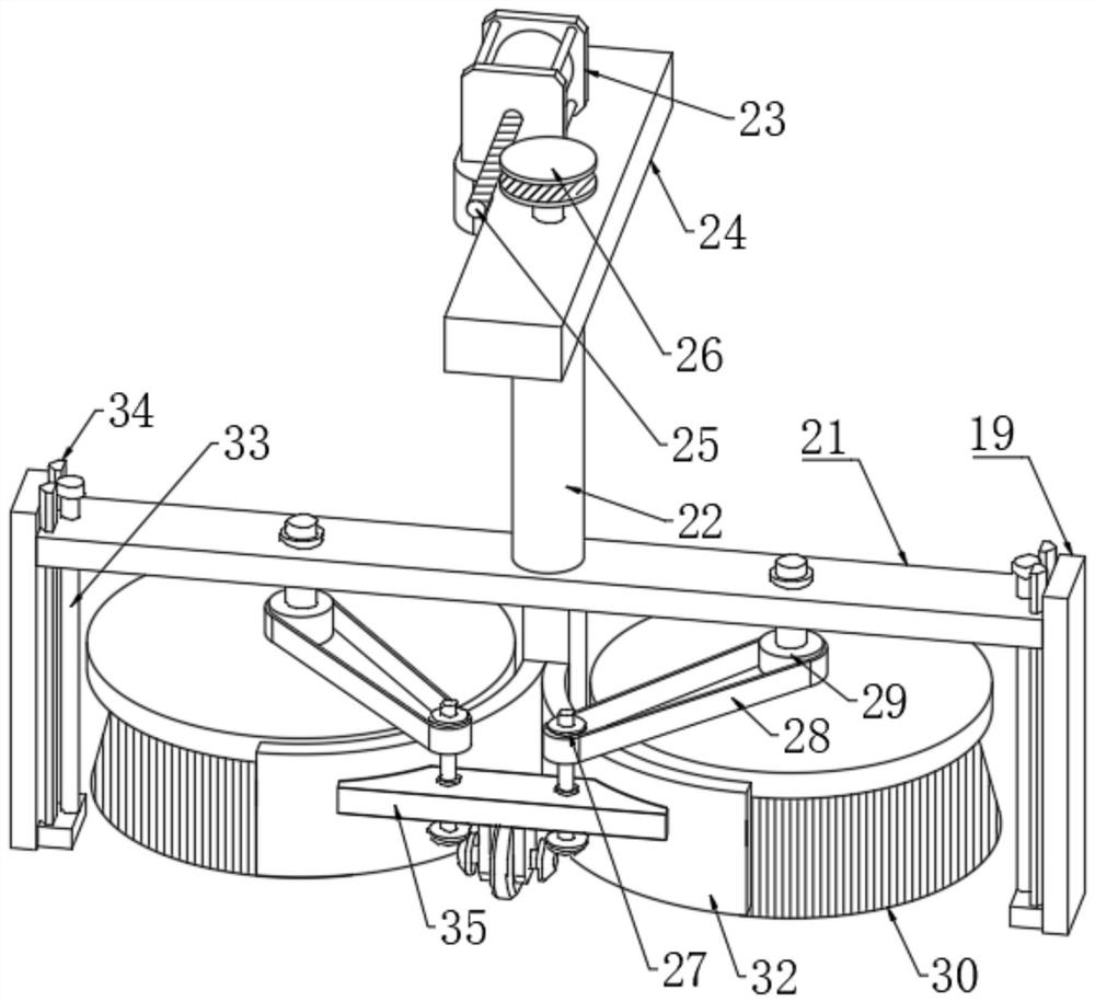
[0031] The cleaning mechanism includes two arc-shaped plates 32 symmetrically fixed on the rear end of the mounting block 31, the rear sides of the two arc-shaped plates 32 are jointly fixedly connected with a connecting block 35, and the lower end of the connecting block 35 is fixedly connected with two fixed blocks, two Between the fixed blocks, a rotating shaft is jointly rotated through the first rolling bearing, and a transmission wheel 39 is fixedly connected to the shaft wall of the rotating shaft. Both ends of the rotating shaft pass through the first rolling bearing and are fixedly connected to the first bevel gear 40. The lower end is connected with two support shafts through the second rolling bearing, the lower ends of the two support shafts are fixedly connected with the second bevel gear 41, the first bevel gear 40 meshes with the second bevel gear 41, and the upper end of the support shaft passes thr...

Embodiment 3

[0033] Embodiment 3: the difference based on embodiment 1 is;

[0034] The traction mechanism includes a brake plate 9 parallel to the front side of the support plate 7, and the opposite side of the brake plate 9 and the support plate 7 is connected with two obliquely arranged pull rods 8 through pin rotation, and the two pull rods 8 are parallel to each other. The front end of the brake plate 9 is symmetrically fixedly connected with two sliding sleeves 10, and the two sliding sleeves 10 are rotatably connected with a connecting shaft 11 through a sealed bearing, and the lower end of one of the connecting shafts 11 passes through the sealed bearing and is fixedly connected with an inverted shaft. U-shaped block 13, the shaft wall of the connecting shaft 11 is fixedly connected with an inverted T-shaped connector 12, the side wall of the vertical part of the T-shaped connector 12 is provided with a plurality of assembly holes, and the side wall of the brake plate 9 passes throu...


PUM


Abstract

The invention relates to the technical field of machine pulsation controllers, and discloses a road surface flatness measuring device which comprises a detection host, a plurality of infrared sensors, a plurality of displacement sensors and a rectangular frame, wherein two vertical rods are fixedly connected to the edge of the upper end of the rectangular frame, and a transverse plate is fixedly connected to the upper ends of the two vertical rods together. The upper end of the transverse plate is fixedly connected with the lower end of the detection host, the lower end of the transverse plate is fixedly connected with a plurality of displacement sensors, a supporting rod is fixedly connected to the center of the rear edge of the upper end of the rectangular frame, and a fixing frame is fixedly connected to the upper side of the rear end of the supporting rod. According to the road surface flatness measuring device, flexible connection between the measuring device and a traction vehicle can be achieved, the situation that the working precision of the measuring device is affected by shaking of the vehicle is prevented, the measuring device can be rapidly lifted to facilitate hauling after measurement is completed, and obstacles at the upper end of a measured road surface can be cleaned when necessary.

Description

technical field [0001] The invention relates to the technical field of pulsation controllers, in particular to a road surface smoothness measuring device. Background technique [0002] The roughness of the road surface is one of the main technical indicators for evaluating the quality of the road surface. It is related to the safety and comfort of driving, the size of the impact force on the road surface and the service life. The uneven road surface will increase the driving resistance and cause additional damage to the vehicle. This kind of vibration will cause driving bumps, affect the speed and safety of driving, and affect the stability of driving and the comfort of passengers. At the same time, the vibration will also exert an impact on the road surface, thereby aggravating the damage of the road surface and automobile parts, the wear of tires, and increasing the consumption of fuel. Moreover, the uneven road surface will also accumulate rainwater, which will accelerat...

Claims


Application Information

Patent Timeline
IPC IPC(8): G01B21/30E01C23/01B08B1/00
CPCG01B21/30E01C23/01B08B1/002
Inventor 黄延姚政
Owner 杭州市城乡建设设计院股份有限公司
Why Eureka
Try Eureka