Visual model structure convenient for high-pressure cyclic heating

A model structure, high-pressure circulation technology, applied in teaching models, wellbore/well components, instruments, etc., can solve the problems of difficult to blow off the gas structure, difficult to disassemble, damage to the spacer glass, etc., to achieve simple and fast operation and increase convenience sexual effect

Active Publication Date: 2021-06-01
JIANGSU UNIPAC SCI RES APP CO LTD
View PDF5 Cites 0 Cited by
  • Summary
  • Abstract
  • Description
  • Claims
  • Application Information

AI Technical Summary

Problems solved by technology

[0003] The existing high-pressure cycle heating visualization model is difficult to blow off excess gas during use, and the structure is complex and difficult to disassemble. The existing high-pressure cycle heating visualization model needs professional and experienced masters to install when installing the spacer glass. Four screw mounts press against two diagonal spacers to seal, resulting in a high risk of breakage of the spacers

Method used


Image

  • Visual model structure convenient for high-pressure cyclic heating
  • Visual model structure convenient for high-pressure cyclic heating
  • Visual model structure convenient for high-pressure cyclic heating

Examples


Embodiment 1

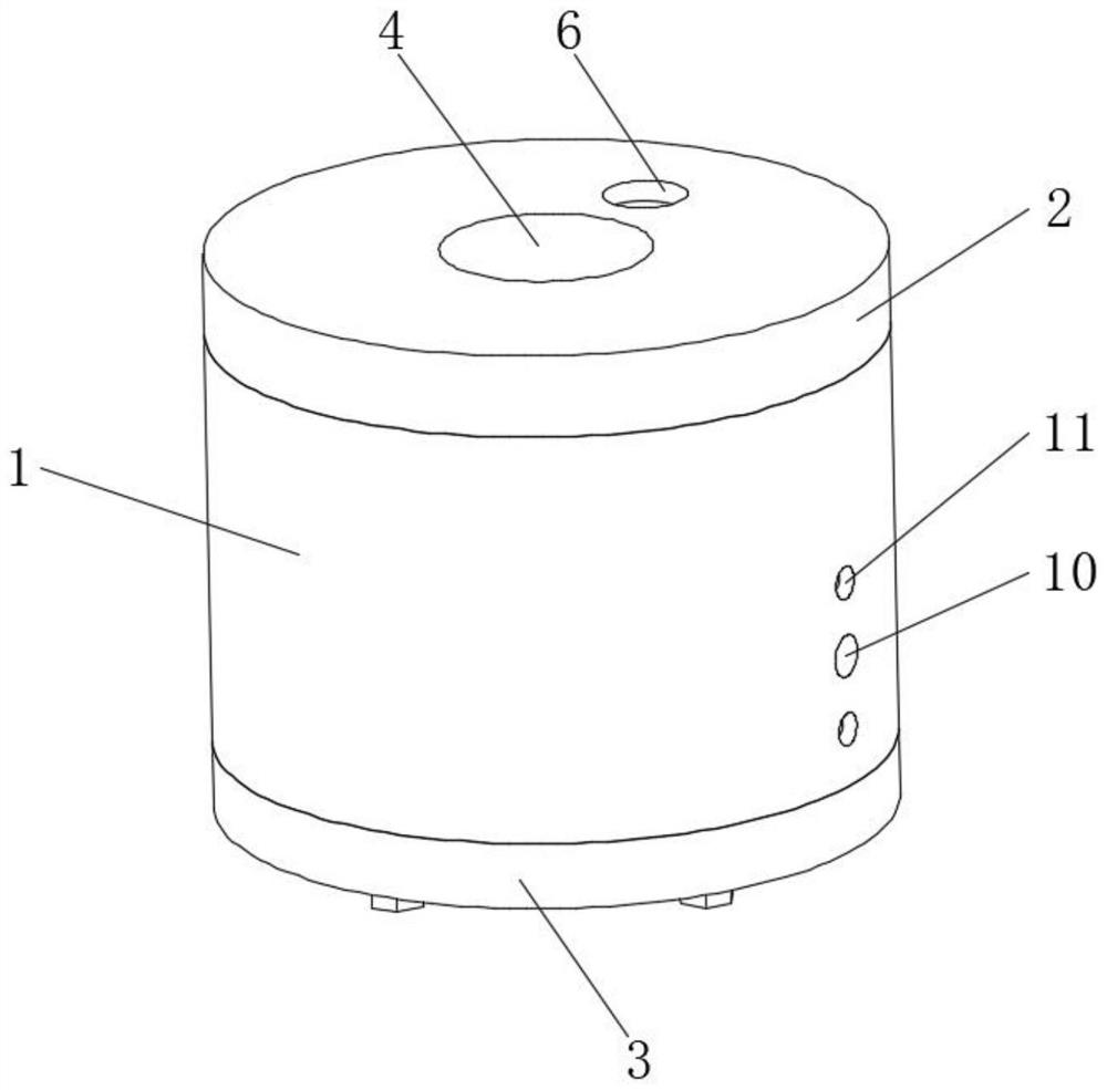
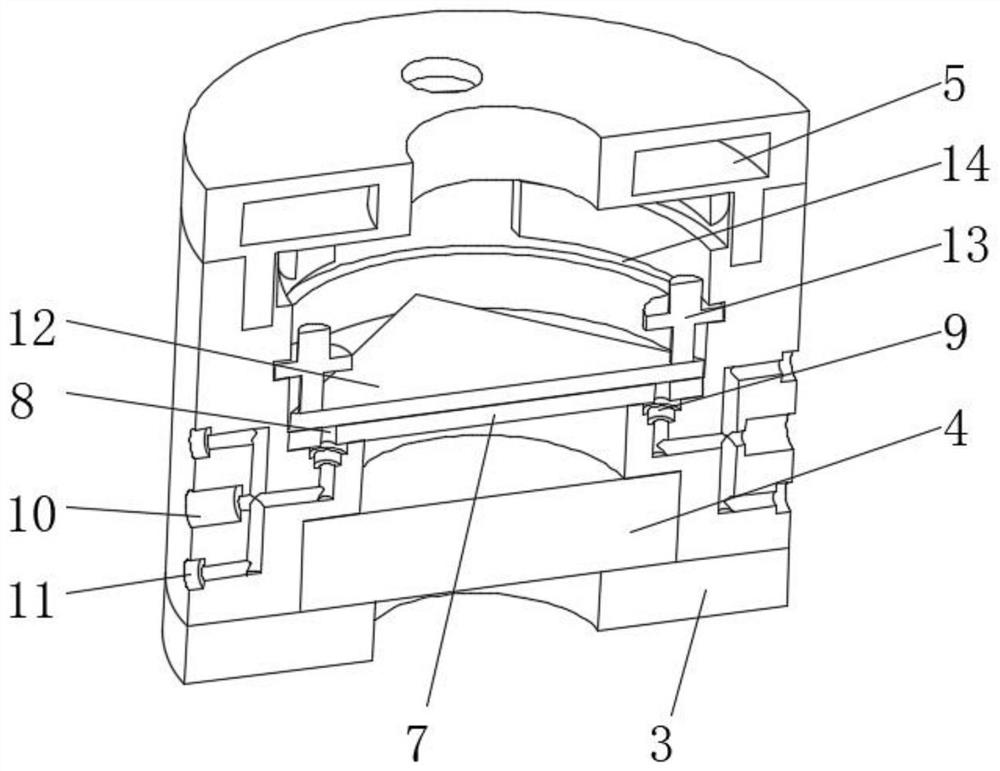
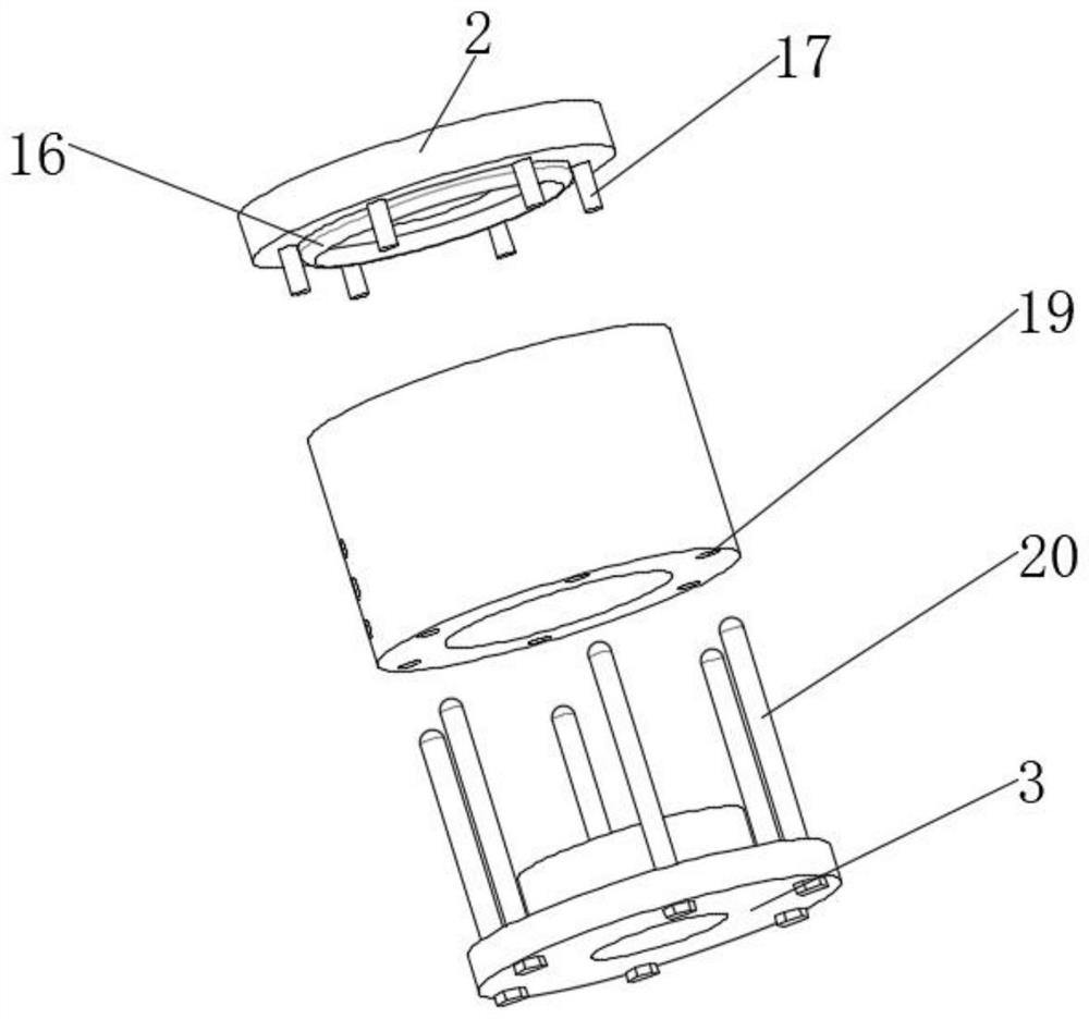
[0023] see Figure 1-4 , a visual model structure convenient for high-pressure cycle heating, including a kettle body 1, the top of the kettle body 1 is provided with an upper kettle cover 2, the lower surface of the kettle body 1 is fixedly connected with several limit bolts 17, and the bottom of the kettle body 1 A glass pressure plate 3 is provided at the end, and a bolt 20 is connected to the glass pressure plate 3. A lower spacer glass 7 is placed in the kettle body 1. An upper spacer glass 12 is arranged above the lower spacer glass 7. The lower spacer glass 7 Both sides of the surface are provided with through holes 8, the inner wall surface of the kettle body 1 is provided with a circular groove 9, the surface of the kettle body 1 is provided with an input port 10, and the input port 10 and the circular groove 9 are connected by a through groove, and the input port 10 The upper and lower sides of the upper and lower sides are provided with outlets 11, the outlets 11 co...

Embodiment 2

[0025] Based on Example 1, such as Figure 1-4 , both sides of the upper surface of the upper spacer glass 12 are fixedly connected with the limiter 13, the inner wall surface of the kettle body 1 is provided with a limiter ring groove 14, the limiter 13 is snapped with the limiter ring groove 14, and the limiter ring groove 14 There are installation notches 15 on one side of the wall, and the number of installation notches 15 is two. Insert the upper spacer glass 12 upper limit member 13 from the installation notch 15 into the limit ring groove 14, and rotate the upper spacer glass 12 The limiting member 13 is engaged with the limiting ring groove 14 to complete the fixing of the limiting member 13 and install the upper spacer glass 12 .

[0026] Working principle: When using the pump device, insert the limit bolt 17 into the limit hole 18 to complete the installation of the upper kettle cover 2, and the sealing ring 16 on the lower surface of the upper kettle cover 2 ensures...


PUM


Abstract

The invention relates to the technical field of visual models, and discloses a visual model structure convenient for high-pressure cyclic heating, the visual model structure convenient for high-pressure cyclic heating comprises a kettle body, and the top end of the kettle body is provided with an upper kettle cover. According to the visual model structure convenient for high-pressure cyclic heating, a through hole, a circular groove, an input port, a discharge port, a limiting bolt, a limiting hole, a mounting screw hole and a bolt are arranged, the limiting bolt is inserted into the limiting hole to complete the mounting of the upper kettle cover, and the sealing ring on the lower surface of the upper kettle cover ensures the sealing performance of the upper kettle cover; a glass pressing plate is mounted at the bottom of the kettle body through threaded connection of the bolt and the mounting screw hole, the whole-course mounting operation is simple and rapid, the mounting convenience is greatly improved, and when the kettle body is added through a heating ring, liquid can be effectively injected into the circular groove from the input port through a through groove and then enters the upper surface of lower spacer glass through the through hole, so that the liquid is prevented from entering the kettle body. And redundant gas can be exhausted through the discharge port.

Description

technical field [0001] The invention relates to the technical field of visualization models, in particular to a visualization model structure that facilitates high-pressure cycle heating. Background technique [0002] Under reservoir conditions (high temperature and high pressure), the real sandstone model is used to study the high-pressure circulation heating experiment of reservoir fluid, which provides a good technical means for the study of multi-phase fluid seepage law. characteristics, and visualization experiments can be carried out under reservoir temperature and pressure. [0003] The existing high-pressure cycle heating visualization model is difficult to blow off excess gas during use, and the structure is complex and difficult to disassemble. The existing high-pressure cycle heating visualization model needs professional and experienced masters to install when installing the spacer glass. Four screws are mounted against two diagonal spacers for sealing, so there...

Claims


Application Information

Patent Timeline
Patent Type & Authority Applications(China)
IPC IPC(8): G09B23/40E21B49/00
CPCG09B23/40E21B49/00
Inventor 吴建何小兵王彩鹏刘永根许小林
Owner JIANGSU UNIPAC SCI RES APP CO LTD
Why Eureka
Try Eureka