Tubular stranding machine for cable processing

A stranding machine and tube type technology, which is used in cable/conductor manufacturing, circuits, electrical components, etc., can solve the problems of labor consumption and low efficiency, and achieve the effect of stable operation, guaranteed work efficiency and high degree of automation.

Inactive Publication Date: 2021-06-01
安徽维尔特仪表线缆有限公司
View PDF11 Cites 2 Cited by
  • Summary
  • Abstract
  • Description
  • Claims
  • Application Information

AI Technical Summary

Problems solved by technology

[0005] The purpose of the present invention is to solve the problem of labor-intensive and low efficiency in the prior art, and propose a tubular stranding machine for cable processing

Method used


Image

  • Tubular stranding machine for cable processing
  • Tubular stranding machine for cable processing
  • Tubular stranding machine for cable processing

Examples


Embodiment 1

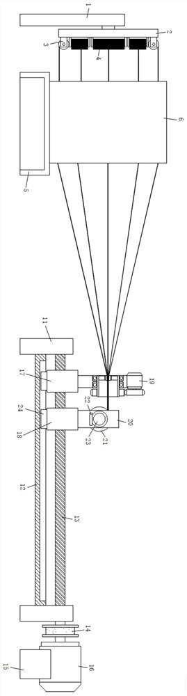
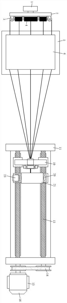
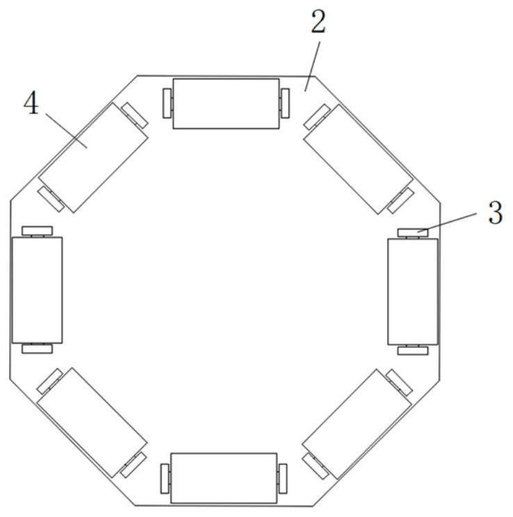
[0031] refer to Figure 1-5 , a tubular stranding machine for cable processing, including a mounting base 1, a pay-off reel 2 is fixedly connected to one side of the upper end of the mount A pay-off roller 4 is connected between the blocks 3, and a mounting frame 5 is arranged on one side of the mounting base 1, and a straightening block 6 is fixed on the top surface of the mounting frame 5, and a cylindrical hole is provided on the extension of the straightening block 6 close to the mounting base 1 7. The inner wall of the cylindrical hole 7 is fixed with a heating sheet 8, and the other end of the straightening block 6 is also provided with a rectangular groove 9 at the extension position. The rectangular groove 9 is connected with the cylindrical hole 7, and the inner walls of the front and rear sides of the rectangular groove 9 rotate The straightening roller 10 is connected, and the side of the mounting frame 5 facing away from the mounting base 1 is also provided with a ...

Embodiment 2

[0034] Such as figure 1 , 2As shown in and 5, this embodiment is basically the same as Embodiment 1. Preferably, the twisting mechanism 19 includes a fixed plate 191, and the middle part of the fixed plate 191 is rotatably connected with a twisting barrel 192, and the twisting barrel 192 is close to the side of the straightening block 6 The inner wall is fixed with electric telescopic rods 193 by screws. There are three electric telescopic rods 193 which are evenly distributed on the inner wall of one side of the twisting tube 192 in a ring shape. The output ends of the electric telescopic rods 193 are fixed with extrusion blocks 194 by screws. , one end of the twisted wire barrel 192 deviates from the straightening block 6 and extends to the outside of the fixed plate 191 and is fixed with an outer ring gear 195 on the outer wall. The screw is fixedly connected with a driving gear 197 , and the driving gear 197 is meshed with the outer ring gear 195 .

[0035] In this embod...

Embodiment 3

[0037] Such as figure 1 with 2 As shown, this embodiment is basically the same as Embodiment 1. Preferably, the front and rear sides of the bottom ends of the first installation strip 17 and the second installation strip 18 are all fixedly connected with the limit block 24, and the front and rear sides of the top of the support plate 12 are also provided with a limit slot. The limiting blocks 24 are all slidably connected in the limiting grooves.

[0038] In this embodiment, the first installation bar 17 and the second installation bar 18 are connected to the support plate 12 through the limit block 24, so that the translation of the first installation bar 17 and the second installation bar 18 is more stable.


PUM


Abstract

A tubular stranding machine for cable processing disclosed by the present invention comprises a mounting base, one side of the upper end of the mounting base is fixedly connected with a pay-off reel, a mounting block is fixed at the extension position of one end of the pay-off reel, a pay-off roller is rotatably connected between the two mounting blocks in the same group, one side of the mounting base is provided with a mounting rack, and the mounting rack is provided with a pay-off roller. A straightening block is fixed to the top face of the mounting frame, a cylindrical hole is formed in the extension portion of the end, close to the mounting base, of the straightening block, heating pieces are fixed to the inner wall of the cylindrical hole, a rectangular groove is further formed in the extension position of the other end of the straightening block and communicates with the cylindrical hole, and straightening rollers are rotationally connected to the inner walls of the front side and the rear side of the rectangular groove. Fixing seats are further arranged on the sides, away from the mounting base, of the mounting frames, and supporting plates are further fixedly connected to the lower ends of the two fixing seats. The stranding machine is reasonable in design, stable in device operation and high in stranding efficiency, and cable raw materials are straightened before stranding, so that the quality of cable stranding is well guaranteed.

Description

technical field [0001] The invention relates to the technical field of cable processing equipment, in particular to a tubular stranding machine for cable processing. Background technique [0002] The production and processing of cables is inseparable from the stranding machine. The stranding machine is a kind of stranding mechanical equipment that can be widely used in various soft and hard conductor wires, so that multiple single conductors are twisted into one strand to meet the technical requirements of the wire. According to the twisting method, the stranding machine can generally be divided into single stranding machine, pair stranding machine, high-speed stranding machine, untwisting machine, cage stranding machine, frame stranding machine, tubular stranding machine and disc stranding machine Among them, the tubular stranding machine is the most widely used, so the research on the tubular stranding machine is particularly important. [0003] After retrieval, the paten...

Claims


Application Information

Patent Timeline
Patent Type & Authority Applications(China)
IPC IPC(8): H01B13/02
CPCH01B13/02
Inventor 陈林森
Owner 安徽维尔特仪表线缆有限公司
Why Eureka
Try Eureka