Auxiliary casing type outer rotor permanent magnet synchronous motor cooling device

A technology for permanent magnet synchronous motors and cooling devices, applied in the direction of electromechanical devices, cooling/ventilation devices, casings/covers/supports, etc., can solve problems such as large winding losses, achieve low manufacturing costs, increase power density, increase The effect of cooling area

Pending Publication Date: 2021-06-01
SHENYANG POLYTECHNIC UNIV
View PDF0 Cites 2 Cited by
  • Summary
  • Abstract
  • Description
  • Claims
  • Application Information

AI Technical Summary

Problems solved by technology

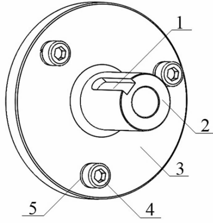
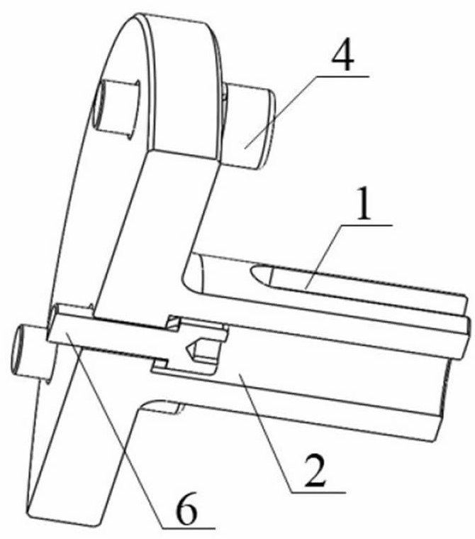
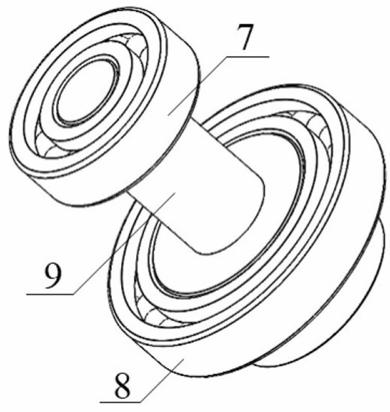
[0005] The present invention aims at the defects existing in the prior art, and provides a novel cooling structure of a high power density permanent magnet motor, which aims at the problem that the winding loss of the outer rotor high power density permanent magnet motor is too large during operation, resulting in excessive local temperature; fully Utilizing the high thermal conductivity of the heat dissipation copper tube, the heat is quickly and efficiently transferred to the outside of the permanent magnet motor, so that the permanent magnet motor is in a suitable operating temperature range, preventing operation failures, ensuring safe and reliable operation of the motor, and ensuring the safety of the motor performance and stability

Method used


Image

  • Auxiliary casing type outer rotor permanent magnet synchronous motor cooling device
  • Auxiliary casing type outer rotor permanent magnet synchronous motor cooling device
  • Auxiliary casing type outer rotor permanent magnet synchronous motor cooling device

Examples


specific Embodiment 1

[0066] Specific embodiment 1: the method for fixing both ends of the heat dissipation copper pipe, the heat-absorbing end of the heat dissipation copper pipe is inserted into the round hole of the yoke of the stator core, and the two adopt interference fit; for a specific example, the diameter of the round hole can be 9.98mm, The outer diameter of the stator core can be 10.0mm, so that the round hole of the stator core yoke and the copper tube can fully contact and transfer heat better. Considering the influence of the processing technology, there is no guarantee that there is an air gap between the two, and it is necessary to inject a thermally conductive adhesive with a high thermal conductivity inside to transfer heat better. The heat release end of the heat dissipation copper tube and the auxiliary casing radiator adopt the same installation process as the round hole of the yoke of the stator core.

specific Embodiment 2

[0067] Specific embodiment 2: winding end potting technology, the temperature rise of the winding end of high power density permanent magnet motor is relatively high, in order to reduce the winding temperature rise, the process of winding end potting is usually adopted, but the existing winding end potting The heat dissipation of the winding end is limited; therefore, in the patent of the present invention, the heat dissipation copper pipe and the winding end are potted together, and the heat at the winding end is transferred to the outside through the heat dissipation copper pipe, which improves the heat dissipation efficiency; at the same time, the potting The glue plays a role in fixing the copper pipe, preventing the heat dissipation copper pipe from vibrating when the motor is running, resulting in a reduction in the heat dissipation efficiency of the heat dissipation copper pipe.

[0068] Auxiliary casing radiator: (1) When the outer rotor permanent magnet motor is runnin...


PUM


Abstract

The invention relates to a high-efficiency cooling heat dissipation structure, in particular to an auxiliary casing type outer rotor permanent magnet synchronous motor cooling device. The safety performance and the stability performance of the motor are guaranteed. The device comprises a permanent magnet motor and a heat dissipation copper pipe, one end of the heat dissipation copper pipe is connected with an auxiliary casing type radiator, the other end of the heat dissipation copper pipe is inserted into a stator iron core yoke portion of a permanent magnet motor, the heat dissipation copper pipe is used for absorbing heat generated in a stator winding and a stator iron core, and the auxiliary casing type radiator increases the heat dissipation area.

Description

technical field [0001] The invention relates to a high-efficiency cooling and heat dissipation structure, in particular to an auxiliary casing type outer rotor permanent magnet synchronous motor cooling device. Background technique [0002] With the rapid development of the manufacturing industry, permanent magnet synchronous motors have been widely used in various new applications such as electric vehicles, rail transit, aerospace vehicles, and industrial robots. In the context of continuous improvement in performance requirements and power density of permanent magnet synchronous motors, this brings new challenges to the electromagnetic design, structural design and heat dissipation design of the motor. [0003] The increase of the power density of the permanent magnet motor means the increase of the copper loss of the internal winding of the motor, the iron loss of the stator and the eddy current loss of the permanent magnet, etc., which directly cause the increase of the ...

Claims


Application Information

Patent Timeline
Patent Type & Authority Applications(China)
IPC IPC(8): H02K9/22H02K5/20H02K9/04H02K3/24H02K5/18
CPCH02K3/24H02K5/18H02K5/20H02K9/04H02K9/22Y02T10/64
Inventor 李岩于占洋王瑾王紫丞郭昊
Owner SHENYANG POLYTECHNIC UNIV
Why Eureka
Try Eureka