
Train communication network architecture based on the Ethernet, method and rail train

A train communication network and train communication technology, applied in the field of EMU train network communication, can solve the problems of initial operation failure, increase fault points, and trains cannot operate normally, and achieve the goal of reducing the impact, reducing the number of nodes, and improving the initial operation efficiency. Effect

Active Publication Date: 2021-06-01
CRRC QINGDAO SIFANG ROLLING STOCK RES INST
View PDF4 Cites 9 Cited by
  • Summary
  • Abstract
  • Description
  • Claims
  • Application Information

AI Technical Summary

Problems solved by technology

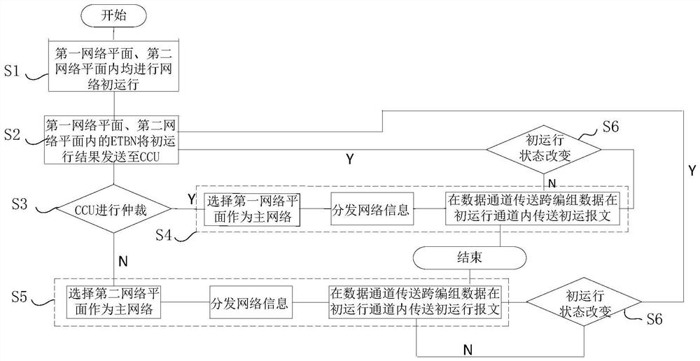
[0003] In the current train Ethernet network system, the Ethernet Train Backbone (ETB) is mostly a linear architecture, and the Ethernet Train Backbone Nodes (ETBN) are connected in series in the linear network. Each train includes Two formations, for the sake of fault tolerance, two ETBN switches are generally deployed in each train formation, respectively connected to the train Ethernet Consist Network (ECN), but in this way: 1. Participate in the train network There are many ETBN switches in the initial operation, and as many as 8 ETBN switches participate in the initial operation when the two trains are reconnected. When the train is first powered on and running, there are many messages, which will easily lead to the failure of the initial operation and increase the failure points; 2. All The initial operation of ETBN switches is carried out in the same physical network. If there are faults that cannot be bypassed, such as cable breakage, loose connectors, and multi-device failures, the initial operation will fail and the train will not be able to operate normally.

Method used


Image

  • Train communication network architecture based on the Ethernet, method and rail train
  • Train communication network architecture based on the Ethernet, method and rail train
  • Train communication network architecture based on the Ethernet, method and rail train

Examples


Embodiment Construction

[0030] In the following, the present invention will be specifically described through exemplary embodiments. It should be understood, however, that elements, structures and characteristics of one embodiment may be beneficially incorporated in other embodiments without further recitation.

[0031] In describing the present invention, it is to be understood that the terms "center", "upper", "lower", "front", "rear", "left", "right", "vertical", "horizontal", The orientations or positional relationships indicated by "top", "bottom", "inner", "outer", etc. are based on the orientations or positional relationships shown in the drawings, and are only for the convenience of describing the present invention and simplifying the description, rather than indicating or implying References to devices or elements must have a particular orientation, be constructed, and operate in a particular orientation and therefore should not be construed as limiting the invention.

[0032] In the descri...


PUM


Abstract

The invention provides a train communication network architecture based on the Ethernet. The train communication network architecture comprises an Ethernet marshalling network; an Ethernet train backbone network which comprises a first network plane and a second network plane, physical layers of the first network plane and the second network plane are mutually independent, and the first network plane and the second network plane share one Ethernet marshalling network, wherein the first network plane and the second network plane are respectively connected in series with two Ethernet train backbone network nodes in each train, each Ethernet train backbone network node is provided with an ETBN switch, and the ETBN switches are connected with the Ethernet marshalling network. The invention further provides a train communication method and a rail train adopting the network architecture. According to the train communication network architecture, the method and the rail train provided by the invention, the number of nodes and the number of messages in initial operation of the train can be effectively reduced, the influence of fault points on train operation is reduced, and safe and reliable train operation is ensured.

Description

technical field [0001] The invention belongs to the technical field of EMU train network communication, and in particular relates to an Ethernet-based train communication network architecture, method and rail train. Background technique [0002] With the promotion and application of Ethernet in the field of trains, it has brought many technological improvements such as large bandwidth, high speed, and intelligent transmission to the rail vehicle on-board network. The initial operation of the Ethernet-based train network can complete dynamic cross-marshalling reconnection networking , intelligent addressing, NAT and other functions. At the same time, the reliability of Ethernet in the initial operation of the train network has attracted more and more attention from the industry. [0003] In the current train Ethernet network system, the Ethernet Train Backbone (ETB) is mostly a linear architecture, and the Ethernet Train Backbone Nodes (ETBN) are connected in series in the li...

Claims


Application Information

Patent Timeline
Patent Type & Authority Applications(China)
IPC IPC(8): H04L12/24B61L27/00
CPCH04L41/0806H04L41/0813H04L41/0654H04L41/0836B61L27/00
Inventor 徐燕芬朱游龙薛树坤
Owner CRRC QINGDAO SIFANG ROLLING STOCK RES INST
Learn More