Garden shrub leveling device
A shrub and garden technology, applied in the field of leveling devices, can solve problems such as increasing the labor intensity of staff
- Summary
- Abstract
- Description
- Claims
- Application Information
AI Technical Summary
Problems solved by technology
Method used
Image
Examples
Embodiment 1
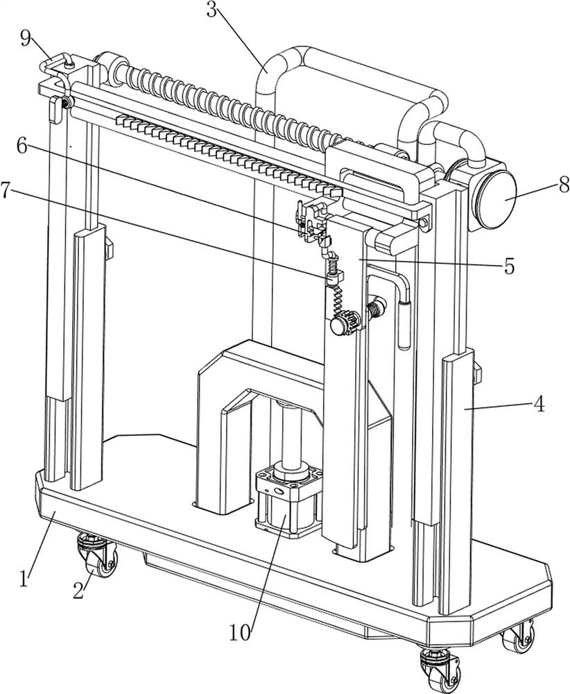
[0065] A garden shrub leveling device, such as figure 1 As shown, it includes a bottom plate 1, a universal wheel 2, a handrail 3, a height adjustment mechanism 4 and a leveling mechanism 5. The bottom left and right sides of the bottom plate 1 are rotatably provided with two universal wheels 2, and the middle of the rear side of the bottom plate 1 is provided with A height adjustment mechanism 4 is arranged between the armrest 3 and the left and right sides of the front part of the bottom plate 1 , and a leveling mechanism 5 is arranged on the upper side of the height adjustment mechanism 4 .
[0066]When people need to level the bushes, they can use this garden bush leveling device. First, pull the handrail 3 and push it to the front of the bushes to be leveled. The operation of the handrail 3 drives the operation of the bottom plate 1 and the rolling of the universal wheel 2, and stops when it arrives. Push the handrail 3, and then adjust the height adjustment mechanism 4 a...
Embodiment 2
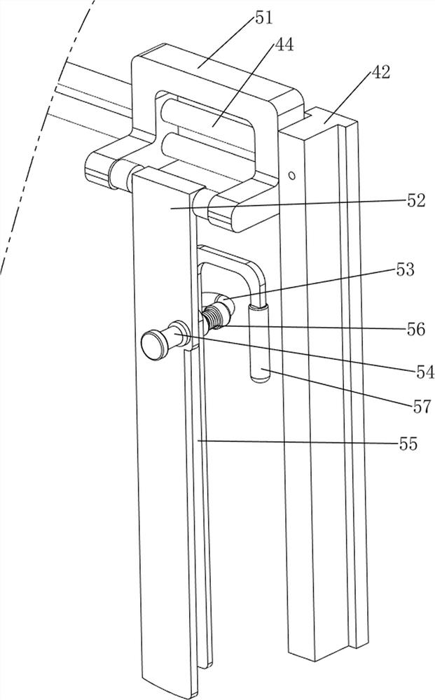
[0068] On the basis of Example 1, as figure 2 and image 3 As shown, the height adjustment mechanism 4 includes a chute 41, a first sliding block 42, a bolt 43 and a slide rail 44. The left and right sides of the bottom plate 1 are provided with a chute 41, and the upper sides of the rear of the chute 41 on both sides are threaded There are bolts 43 on the two sides, first sliding blocks 42 are slidably provided on the upper sides of the sliding grooves 41 on both sides, and two sliding rails 44 are provided between the upper parts of the first sliding blocks 42 on both sides.
[0069] People need to adjust according to the height of the bushes. When the bushes are short, people need to turn the bolts 43 to make the bolts 43 rotate backward, so that the first slider 42 slides down, and then drives the slide rail 44 to move down. When it is adjusted to be flush with the bushes, then turn the bolt 43 to rotate forward, so that the bolt 43 can clamp the first slider 42. After l...
Embodiment 3
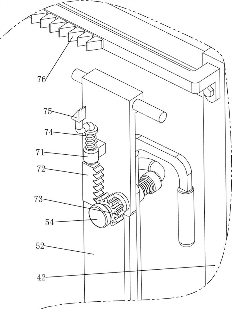
[0073] On the basis of Example 2, as Figure 4-Figure 8 As shown, a locking mechanism 6 is also included. The locking mechanism 6 includes a mounting bracket 61, a movable rod 62 and a first pressure spring 63. A mounting bracket 61 is provided on the front side of the lower left part of the second slider 51. The side sliding type is provided with a movable rod 62 , and two first pressure springs 63 are wound around the lower side of the movable rod 62 .
[0074] When the installation block 52 needs to be turned up, people manually pull the movable rod 62 to the left, so that the first pressure spring 63 is compressed, so that the lower side of the movable rod 62 releases the installation block 52. When the installation block 52 is turned to a horizontal state When people let go, the first pressure spring 63 resets and drives the movable rod 62 to move to the right, and clamps the mounting block 52, so that people do not need to drag the mounting block 52 to the left all the t...
PUM
 Abstract
Description
Claims
Application Information
 - R&D
- Intellectual Property
- Life Sciences
- Materials
- Tech Scout
- Unparalleled Data Quality
- Higher Quality Content
- 60% Fewer Hallucinations
Browse by: Latest US Patents, China's latest patents, Technical Efficacy Thesaurus, Application Domain, Technology Topic, Popular Technical Reports.
© 2025 PatSnap. All rights reserved.Legal|Privacy policy|Modern Slavery Act Transparency Statement|Sitemap|About US| Contact US: help@patsnap.com


