
Working method of automatic adhesive coating device

A technology of encapsulation device and working method, which is applied to the device and coating of the surface coating liquid, which can solve the problems of burden, inconvenient placement, time-consuming and laborious, etc., and achieve the effect of improving work efficiency and stable and reliable structure

Inactive Publication Date: 2021-06-04
宁波市鄞州承润科技有限公司
View PDF0 Cites 0 Cited by
  • Summary
  • Abstract
  • Description
  • Claims
  • Application Information

AI Technical Summary

Problems solved by technology

In order to prevent the edge of the punch from being damaged, each punch will be protected with hot melt adhesive before shipment, but the staff needs to pick up the punch and put the edge of the punch into the hot melt adhesive. After wrapping the knife edge with hot melt glue, place the punch upside down on the platform. The hot melt glue needs to be left to dry for a while, and the place to hang it will definitely be close first and then far away. It is more and more inconvenient to place and disorderly. , and it will be knocked down if you are not careful, and it will take a long time to pick up, put down and place, which will be time-consuming and labor-intensive, and will also burden the staff's arms

Method used


Image

  • Working method of automatic adhesive coating device
  • Working method of automatic adhesive coating device
  • Working method of automatic adhesive coating device

Examples


Embodiment Construction

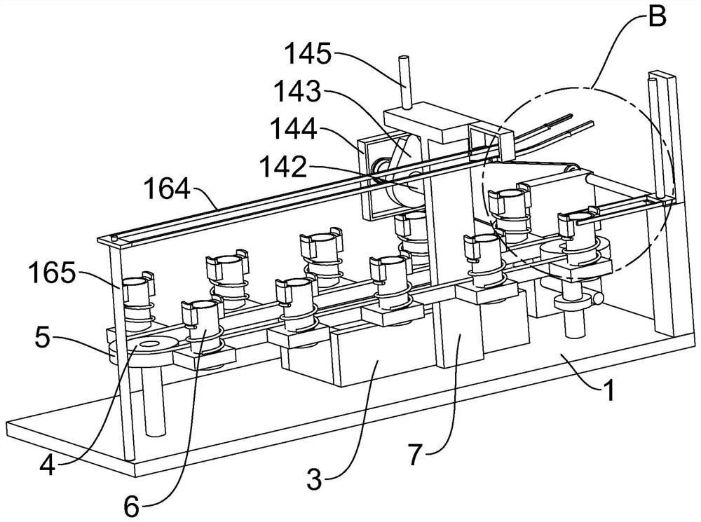
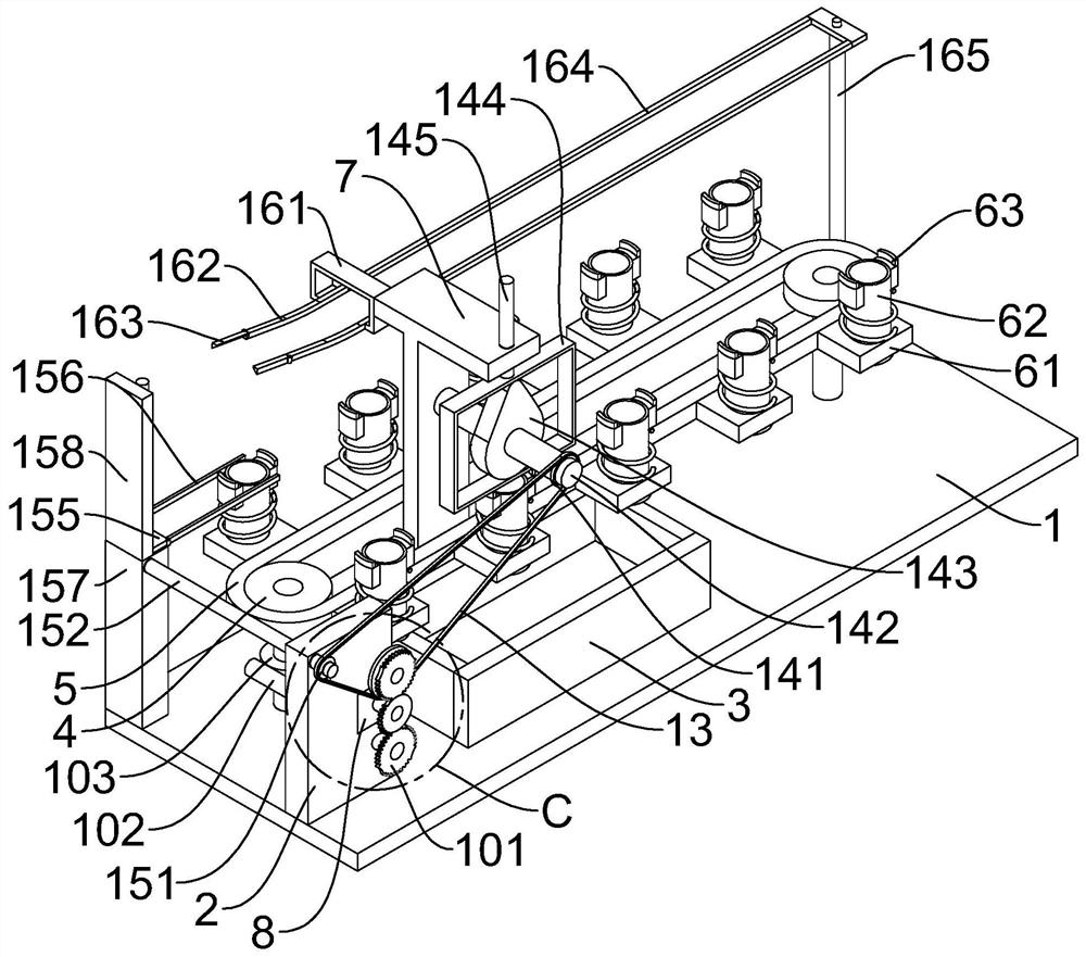
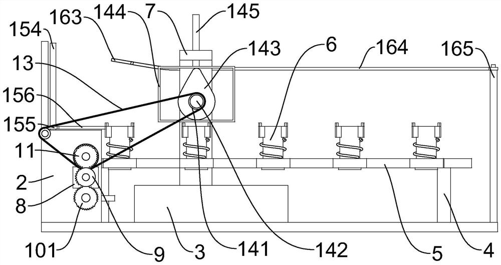
[0033] Such as Figure 1 to Figure 15 As shown, a working method of an automatic encapsulation device, the encapsulation device includes a base 1, the upper end of the base 1 is provided with a vertical block 2, the upper end of the base 1 is provided with a glue pool 3 on the right side of the vertical block 2, and the upper end of the base 1 The left and right sides of the body are symmetrically and rotationally provided with transmission teeth 4, and a transmission chain 5 is connected between the two transmission teeth 4, and telescopic parts 6 are evenly distributed on the transmission chain 5, and the upper end of the base 1 is provided with a T-shaped fixed block 7 , the vertical block 2 is provided with a stepping motor 8, the output shaft of the stepping motor 8 is keyed with an incomplete gear 9, and the vertical block 2 is provided with an intermittent gear that matches the incomplete gear 9 and the transmission tooth 4 on the left side. Drive assembly 10, the upper...


PUM


Abstract

The invention discloses a working method of an automatic adhesive coating device. The working method comprises the following specific step I of continuously putting punches into a telescopic pipe on the leftmost side of the front row; the step II of driving an incomplete gear by a stepping motor to rotate anticlockwise, driving transmission gears and a conveying chain to rotate by the incomplete gear through an intermittent driving assembly, so that the punches are rotated intermittently; and the step III of driving a cog belt to rotate by the incomplete gear through a second locking gear and a large gear, and pressing the punches in the telescopic pipe to dip in an adhesive pool by the cog belt through a pressing assembly. The method has the advantages that the structure is stable and reliable, and the punches can be automatically rotated in sequence, pressed into the adhesive pool and dipped with hot melt adhesive; the punches are raised and reset, and in the pressing and rising process of the punches, two lifting strips are raised to erect the punches; after the two lifting strips are descent and reset, the punches are sequentially arranged on a concave part, meanwhile, follow-up packaging work is facilitated; and the working efficiency is improved.

Description

technical field [0001] The invention relates to the field of punch processing, in particular to a working method of an automatic rubber wrapping device. Background technique [0002] The punch is a metal part on the stamping die in a mechanical tool. It is installed on the stamping die for continuous punching and punching, so that the processed material is separated or deformed to obtain the desired finished or semi-finished product. In order to prevent the edge of the punch from being damaged, each punch will be protected with hot melt adhesive before shipment, but the staff needs to pick up the punch and put the edge of the punch into the hot melt adhesive. After wrapping the knife edge with hot melt glue, place the punch upside down on the platform. The hot melt glue needs to be left to dry for a while, and the place to hang it will definitely be close first and then far away. It is more and more inconvenient to place and disorderly. , and it will be knocked down if you ...

Claims


Application Information

Patent Timeline
Patent Type & Authority Applications(China)
IPC IPC(8): B05C3/02B05C13/02
CPCB05C3/02B05C13/02
Inventor 不公告发明人
Owner 宁波市鄞州承润科技有限公司
Learn More