
Automatic efficient gluing equipment for electronic components

An electronic component and high-efficiency technology, used in coatings, devices that apply liquid to surfaces, etc., can solve problems such as the inability to achieve higher precision and accurate gluing operations, and the inconvenience of gluing heads close to the pin position.

Inactive Publication Date: 2021-06-04
青岛蔷薇优品电子商务有限公司
View PDF12 Cites 0 Cited by
  • Summary
  • Abstract
  • Description
  • Claims
  • Application Information

AI Technical Summary

Problems solved by technology

[0005] In order to solve the above technical problems, the present invention provides a high-efficiency gluing equipment for automatic electronic components to solve the problem that when the automatic electronic component gluing equipment in the above patent is in use, the components with the pins on the inner side are gluing , the original vertically set gluing head is not convenient to be close to the position of the pin, and cannot realize the problem of gluing operation with higher precision and accurate position

Method used


Image

  • Automatic efficient gluing equipment for electronic components
  • Automatic efficient gluing equipment for electronic components
  • Automatic efficient gluing equipment for electronic components

Examples


Embodiment

[0033] as attached figure 1 to attach Figure 8 Shown:

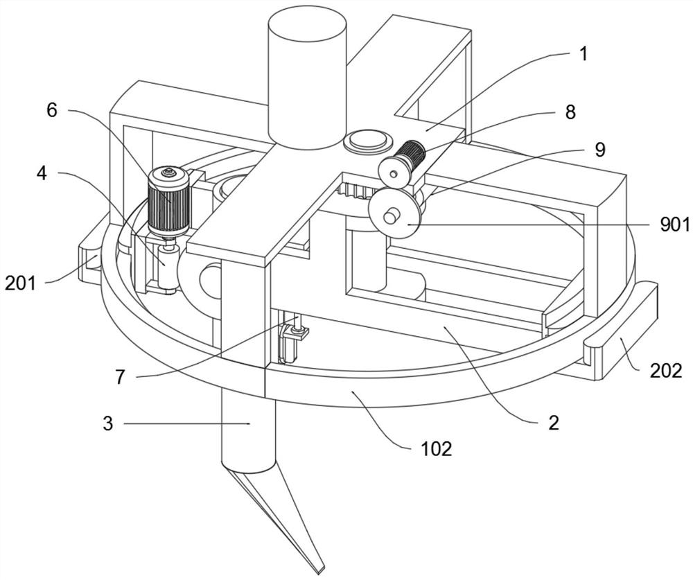
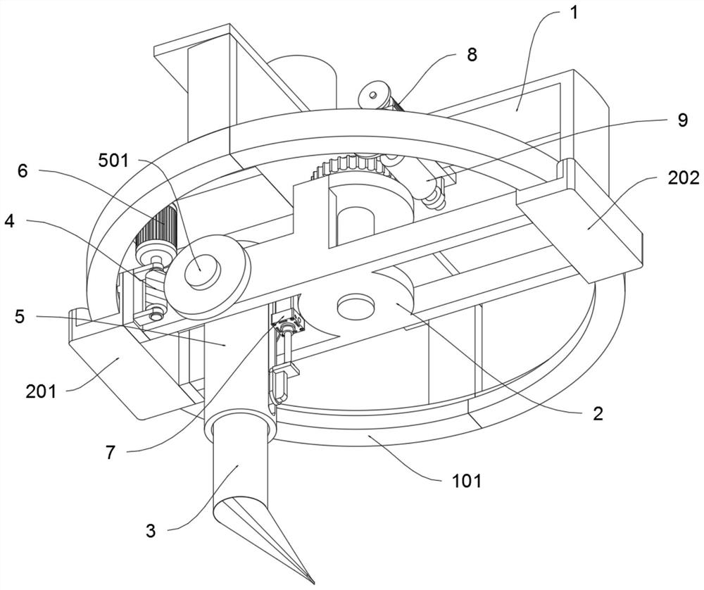
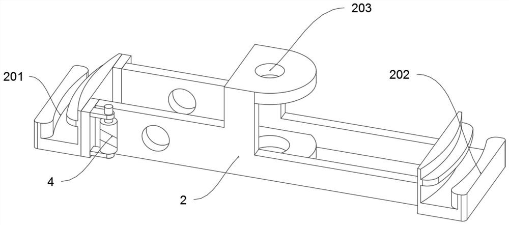
[0034] The present invention provides a high-efficiency gluing equipment for automatic electronic components, including an upper connecting frame 1, a gluing head 3, a lower worm 4, a telescopic cylinder 5, a lower driving part 6, a telescopic driving part 7, an upper driving part 8, and an upper worm 9. The movable rotating rod 101 of the upper connecting frame 1 is fixedly connected in the middle fixing hole 203 of the rotating frame 2 through interference fit, and the two ends of the rotating frame 2 are slidably connected to the annular bracket 102 of the upper connecting frame 1; the lower worm The two ends of 4 are connected to the inner side of the rotating frame 2 through bearing rotation; the two sides of the upper end of the telescopic tube 5 are connected to the left side of the rotating frame 2 through bearing rotation, and the side worm wheel 5021 of the telescopic tube 5 is engaged with the lower worm 4; ...


PUM


Abstract

The invention provides automatic efficient gluing equipment for electronic components. The equipment comprises an upper connecting frame, a gluing head, a lower worm, a telescopic cylinder, a lower driving part, a telescopic driving part, an upper driving part and an upper worm. A movable rotating rod of the upper connecting frame is fixedly connected into a middle fixing hole of a rotating frame in an interference fit mode, and the two ends of the rotating frame are connected to an annular support of the upper connecting frame in a sliding mode. The two ends of the lower worm are rotatably connected to the inner side of the rotating frame through bearings. The two sides of the upper end of a telescopic cylinder are rotatably connected to the left side of the rotating frame through bearings, and a side worm gear of the telescopic cylinder is engaged with the lower worm. The gluing head is rotatably connected to the interior of the telescopic cylinder. The lower driving part is arranged above the rotating frame, and an output shaft of the lower driving part is fixedly connected to the upper end of a shaft of the lower worm. The inclination angle of the lower end of the gluing head can be changed by adjusting the angle of the side worm gear, so that the gluing head is easier to get close to the connecting end of the electronic elements with inner pins, and the pins of the electronic elements are further accurately glued.

Description

technical field [0001] The invention belongs to the technical field of gluing equipment for electronic components, and more specifically relates to an automatic high-efficiency gluing equipment for electronic components. Background technique [0002] Electronic components are components of electronic components and small electrical machines and instruments. They are often composed of several parts and can be used in similar products; they often refer to certain parts in industries such as electrical appliances, radios, and instruments, such as capacitors and transistors. The general term for sub-components such as hairsprings, hairsprings, etc. Commonly used are diodes, etc. During the production of electronic components, it is necessary to apply glue on the surface of electronic components to meet the corresponding production process requirements, while the existing Gluing equipment often has disadvantages such as uneven gluing, labor-intensive, complicated operation, and i...

Claims


Application Information

Patent Timeline
IPC IPC(8): B05C5/02B05C11/10
CPCB05C5/0212B05C11/1002
Inventor 程杨
Owner 青岛蔷薇优品电子商务有限公司
Learn More