A method for machining shallow grooves on retaining rings

A processing method and shallow groove technology, applied in the field of parts processing, can solve the problems of poor openness, the surface roughness of shallow grooves is difficult to reach Ra3.2, and the processing efficiency of shallow grooves is reduced, so as to avoid secondary grinding and improve processing. The effect of efficiency

Active Publication Date: 2022-07-05
CHINA HANGFA GUIZHOU LIYANG AVIATION POWER CO LTD
View PDF7 Cites 0 Cited by
  • Summary
  • Abstract
  • Description
  • Claims
  • Application Information

AI Technical Summary

Problems solved by technology

[0002] In order to meet some requirements, it is necessary to process shallow grooves on the part retaining ring of the aero-engine, such as figure 1 As shown, due to the poor opening of the shallow groove, and the axial sinking depth of the shallow groove is 0.3mm, while the height of the shallow groove axially above is only 4.7mm, ordinary tools cannot enter due to its poor openness. , when processing shallow grooves in the prior art, it is necessary to make non-standard tools for profiling according to the shape of shallow grooves. After non-standard tools use profiling to process shallow grooves, there will be ripples on the surface of shallow grooves, resulting in The surface roughness is difficult to meet the requirements of Ra3.2, and it is necessary to use gauze to grind the surface of the shallow groove twice, resulting in a decrease in the processing efficiency of the shallow groove

Method used


Image

  • A method for machining shallow grooves on retaining rings
  • A method for machining shallow grooves on retaining rings

Examples


Embodiment 1

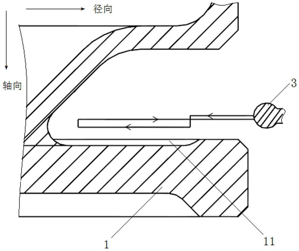
[0032] The invention relates to a processing method for a shallow groove on a retaining ring. The steps include the following:

[0033] Step 1: The retaining ring 1 is fixed on the rotating shaft of the lathe, the round head turning tool 3 is fixed on the tool, and the round head turning tool 3 is aligned with the outer end of the shallow groove to be processed;

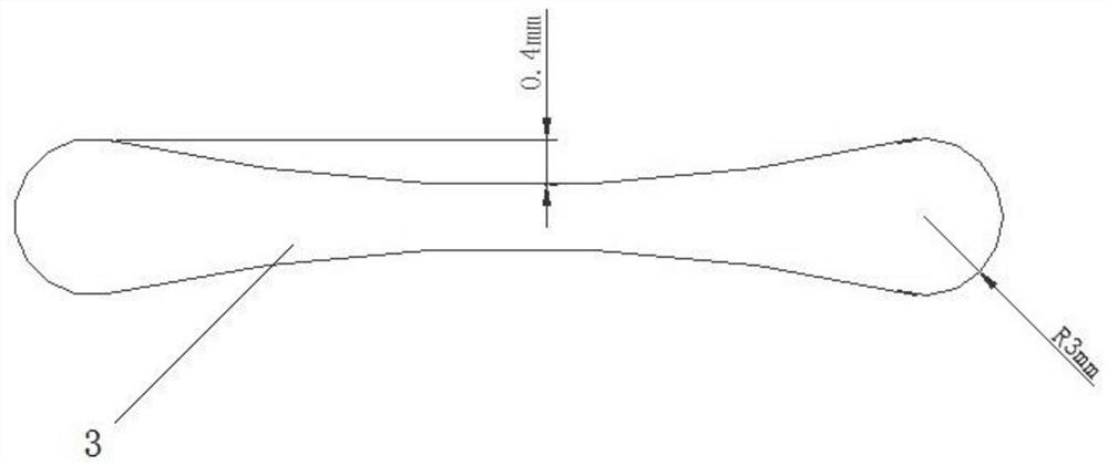
[0034] Step 2: The retaining ring 1 rotates at a speed of 33r / min on the axial center line. If the speed is too fast, the tool wears quickly, and the surface of the tool is prone to local thermal hardening, which affects the quality of the machined surface, and the low speed reduces the production efficiency; The round head of the knife 3 is axially approaching the shallow groove, and the amount of the close back knife is 0.2mm. The knife is manually polished with a polishing wheel to grind the side of the ball-end blade, and the blade has poor rigidity. This cutting amount; the 0.4mm unilateral clearance on the rou...

Embodiment 2

[0037] The invention relates to a processing method for a shallow groove on a retaining ring. The steps include the following:

[0038] Step 1: The retaining ring 1 is fixed on the rotating shaft of the lathe, the round head turning tool 3 is fixed on the tool, and the round head turning tool 3 is aligned with the outer end of the shallow groove to be processed;

[0039] Step 2: The retaining ring 1 rotates at a speed of 32r / min on the axial centerline. If the speed is too fast, the tool wears quickly, and the surface of the tool is easy to form local thermal hardening, which affects the quality of the machined surface. Low speed reduces production efficiency; The round head of the knife 3 is axially approaching the shallow groove, and the amount of the close knife is 0.16mm. The knife is manually polished with a polishing grinding wheel to grind the side of the ball-end blade. The rigidity of the blade is poor. This cutting amount; the 0.4mm unilateral clearance on the round...

Embodiment 3

[0042] The invention relates to a processing method for a shallow groove on a retaining ring. The steps include the following:

[0043] Step 1: The retaining ring 1 is fixed on the rotating shaft of the lathe, the round head turning tool 3 is fixed on the tool, and the round head turning tool 3 is aligned with the outer end of the shallow groove to be processed;

[0044] Step 2: The retaining ring 1 rotates at a speed of 45r / min on the axial centerline. If the speed is too fast, the tool wears quickly, and the surface of the tool is prone to local thermal hardening, which affects the quality of the machined surface, and the low speed reduces the production efficiency; The round head of the knife 3 is axially approaching the shallow groove, and the amount of the close back knife is 0.1mm. The knife is manually polished with a polishing grinding wheel to grind the side of the ball-end blade. The rigidity of the blade is poor. This cutting amount; the 0.4mm unilateral gap on the...


PUM


Abstract

The invention discloses a processing method for a shallow groove on a retaining ring. The steps include the following: step 1: the guard ring is fixed on the rotating shaft of the lathe, the round head turning tool is fixed on the tool, and the round head turning tool is aligned with the outer end of the shallow groove to be machined; step 2: the guard ring is axially arranged. The center line rotates at a speed of 33~45r / min; the round head of the round head turning tool is axially close to the shallow groove, and the approaching back cutting amount is 0.1mm~0.2mm; the 0.4mm unilateral clearance on the round head turning tool The shallow groove is processed by cutting, and the feed rate is 0.1mm / min~0.12mm / min along the radial direction of the guard ring; the shallow groove on the guard ring is processed and formed, and the surface roughness of the shallow groove is Ra1.6~Ra3. 2. It meets the requirement that the roughness of the surface of the shallow groove reaches Ra3.2; it solves the problem that the surface of the shallow groove will be corrugated when the non-standard tool is used for profiling according to the shape of the shallow groove, and avoids the need to use gauze for the shallow groove. The groove surface is polished for a second time, which improves the processing efficiency; Step 3: The round head turning tool rises in the axial direction away from the shallow groove, and then exits from the top of the shallow groove.

Description

technical field [0001] The invention relates to a processing method for a shallow groove on a retaining ring, belonging to the technical field of parts processing. Background technique [0002] In order to meet some requirements, it is necessary to machine shallow grooves on the part retaining ring of aero-engine, such as figure 1 As shown in the figure, due to the poor openness of the shallow groove, the depth of the axial subsidence of the shallow groove is 0.3mm, and the height of the shallow groove above the axial direction is only 4.7mm, and the general tool cannot enter due to its poor openness. , When processing shallow grooves in the prior art, it is necessary to make non-standard tools to carry out profiling according to the shape of the shallow grooves. The roughness of the surface is difficult to meet the requirement of Ra3.2, and it is necessary to use gauze to grind the surface of the shallow groove for a second time, which will reduce the processing efficiency...

Claims


Application Information

Patent Timeline
Patent Type & Authority Patents(China)
IPC IPC(8): B23B1/00B23B27/06
CPCB23B1/00B23B27/06B23B2222/28
Inventor 朱建亚王玉泉张洪钟磊陶建民欧阳克良孙少鹏
Owner CHINA HANGFA GUIZHOU LIYANG AVIATION POWER CO LTD
Why Eureka
Try Eureka