New material grinding equipment

A new material and equipment technology, applied in non-rotational vibration suppression, grain processing, etc., can solve problems such as insufficient grinding, reduced grinding efficiency, shaking of grinding equipment, etc., to avoid insufficient grinding, reduce labor intensity, and reduce grinding costs Effect

Inactive Publication Date: 2021-01-29
上安实业江苏有限公司
View PDF0 Cites 0 Cited by
  • Summary
  • Abstract
  • Description
  • Claims
  • Application Information

AI Technical Summary

Problems solved by technology

[0002] Grinding is a unit operation that reduces solid matter into smaller particles. To grind different substances, humans use various grinders, including manual mortars, mills driven by animals, wind or water, and electric machines driven by electricity. Grinding, etc. During the grinding process of new materials, the grinding equipment used is not conducive to adjusting the distance between the bottom end of the hammer body and the inner bottom end of the discharge box, and is not conducive to grinding new materials, resulting in insufficient grinding. It causes secondary grinding, reduces the grinding efficiency, and increases labor intensity and grinding cost. At the same time, during the grinding process of new materials, due to the collision between the hammer body and the new material, the grinding equipment shakes, which is not conducive to the stability of the grinding equipment.

Method used


Image

  • New material grinding equipment
  • New material grinding equipment
  • New material grinding equipment

Examples


Embodiment Construction

[0015] The following will clearly and completely describe the technical solutions in the embodiments of the present invention with reference to the accompanying drawings in the embodiments of the present invention. Obviously, the described embodiments are only some of the embodiments of the present invention, not all of them. Based on the embodiments of the present invention, all other embodiments obtained by persons of ordinary skill in the art without making creative efforts belong to the protection scope of the present invention.

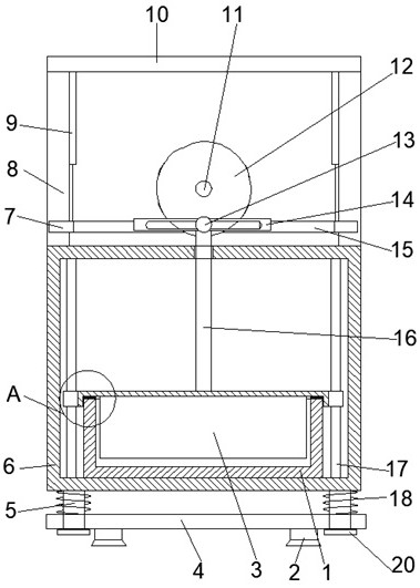
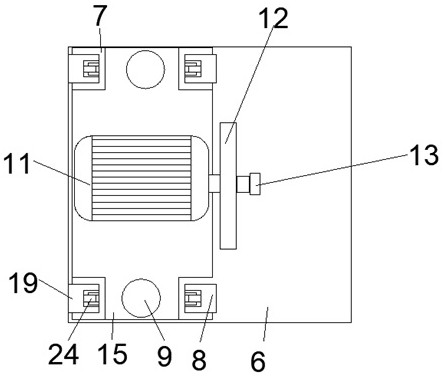
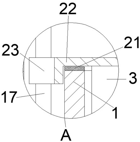
[0016] see Figure 1-3 , the present invention provides a technical solution: a new material grinding equipment, including a discharge box 1, a support seat 2, a hammer block 3, a bottom plate 4, a fixed rod 5, a box body 6, a U-shaped plate 7, a first support leg 8. Hydraulic telescopic rod 9, top plate 10, motor 11, turntable 12, T-bar 13, slide plate 14, moving plate 15, connecting rod 16, slide bar 17, spring 18, second support leg 19, baffle...


PUM


Abstract

The invention discloses new material grinding equipment. The new material grinding equipment comprises a discharge box, a support seat, a hammer block, a bottom plate, fixing rods, a box body, U-shaped plates, first support legs, hydraulic telescopic rods, a top plate, a motor, a turn table, a T-shaped rod, a sliding plate, a moving plate, a connecting rod, sliding rods, springs, second support legs, baffle plates, wearing pads, covers, sliding blocks and idler wheels, wherein small holes are formed in four corners of the edges of the bottom plate; the bottom ends of the fixing rods penetratethrough the small holes formed in the four corners of the edges of the bottom plate and are fixedly connected with the top ends of the baffle plates through bolts, and the top ends of the fixing rodsare fixedly connected with the four corners of the bottom end of the box body through bolts; and the inner bottom end of the box body is fixedly connected with the bottom end of the discharge box through bolts. The new material grinding equipment is simple in structure and convenient to use; shaking of the new material grinding equipment caused by a hammer body in the new material grinding processis avoided; and meanwhile, the hydraulic telescopic rods are arranged, so that the distance between the bottom end of the hammer body and the inner bottom end of the discharge box can be adjusted, and the new material can be fully ground.

Description

technical field [0001] The invention relates to the technical field of grinding equipment, in particular to a new material grinding equipment. Background technique [0002] Grinding is a unit operation that reduces solid matter into smaller particles. To grind different substances, humans use various grinders, including manual mortars, mills driven by animals, wind or water, and electric machines driven by electricity. Grinding, etc. During the grinding process of new materials, the grinding equipment used is not conducive to adjusting the distance between the bottom end of the hammer body and the inner bottom end of the discharge box, and is not conducive to grinding new materials, resulting in insufficient grinding. It causes secondary grinding, reduces the grinding efficiency, and increases labor intensity and grinding cost. At the same time, during the grinding process of new materials, due to the collision between the hammer body and the new material, the grinding equip...

Claims


Application Information

Patent Timeline
IPC IPC(8): B02C1/14F16F15/04
CPCB02C1/14F16F15/04
Inventor 不公告发明人
Owner 上安实业江苏有限公司
Why Eureka
Try Eureka