
Automatic tail drill equipment for horizontal lathe and horizontal lathe

A horizontal lathe, automatic technology, applied in the direction of drilling/drilling equipment, metal processing equipment, boring/drilling device, etc., can solve the problems of high labor intensity and low production efficiency, so as to reduce labor intensity and improve production efficiency , Optimize the effect of working mode

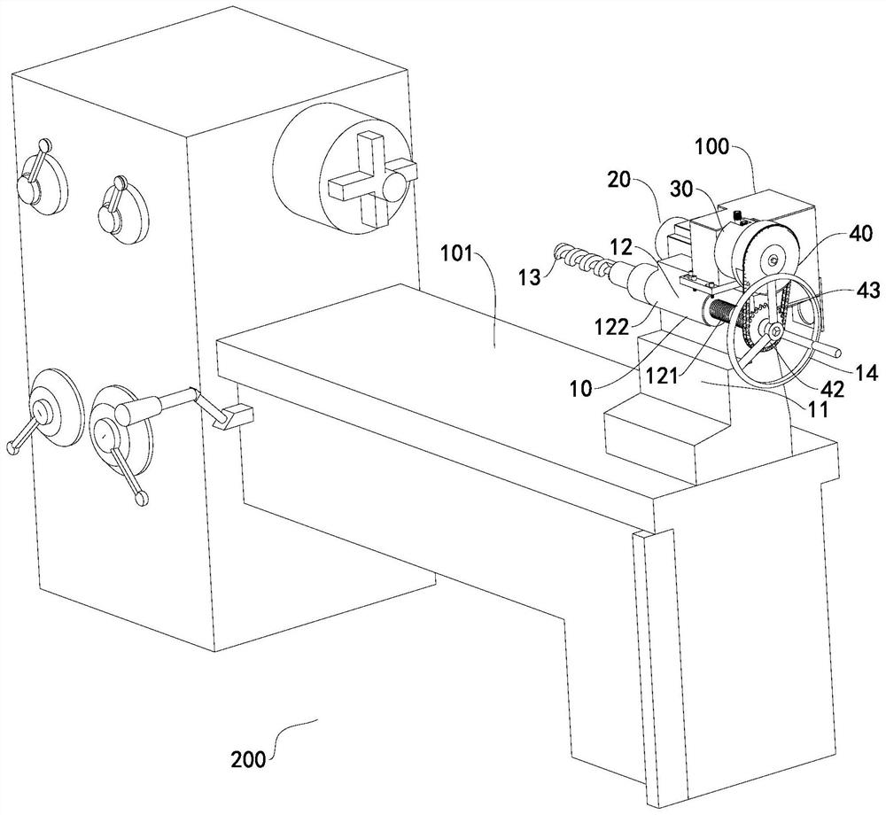
Inactive Publication Date: 2021-06-04
宁波市鄞州塘溪银宏机械厂
View PDF0 Cites 2 Cited by
  • Summary
  • Abstract
  • Description
  • Claims
  • Application Information

AI Technical Summary

Problems solved by technology

[0004] Since the tool relies on the manual crank to expand and contract, the labor intensity is high and the production efficiency is low

Method used

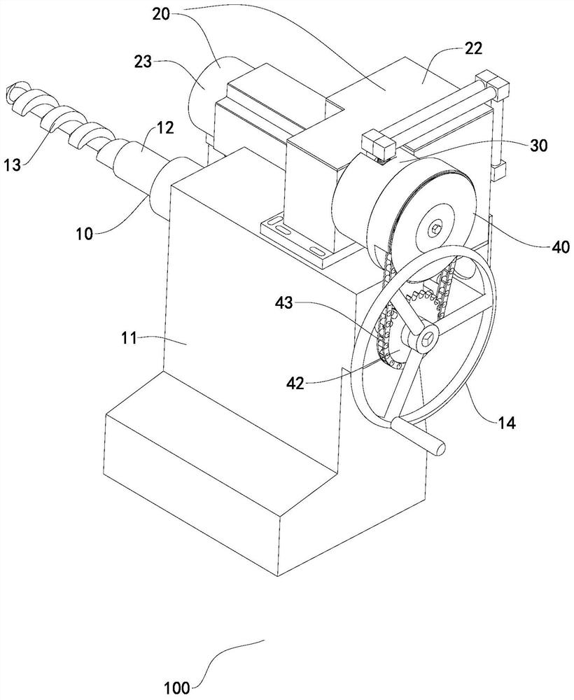
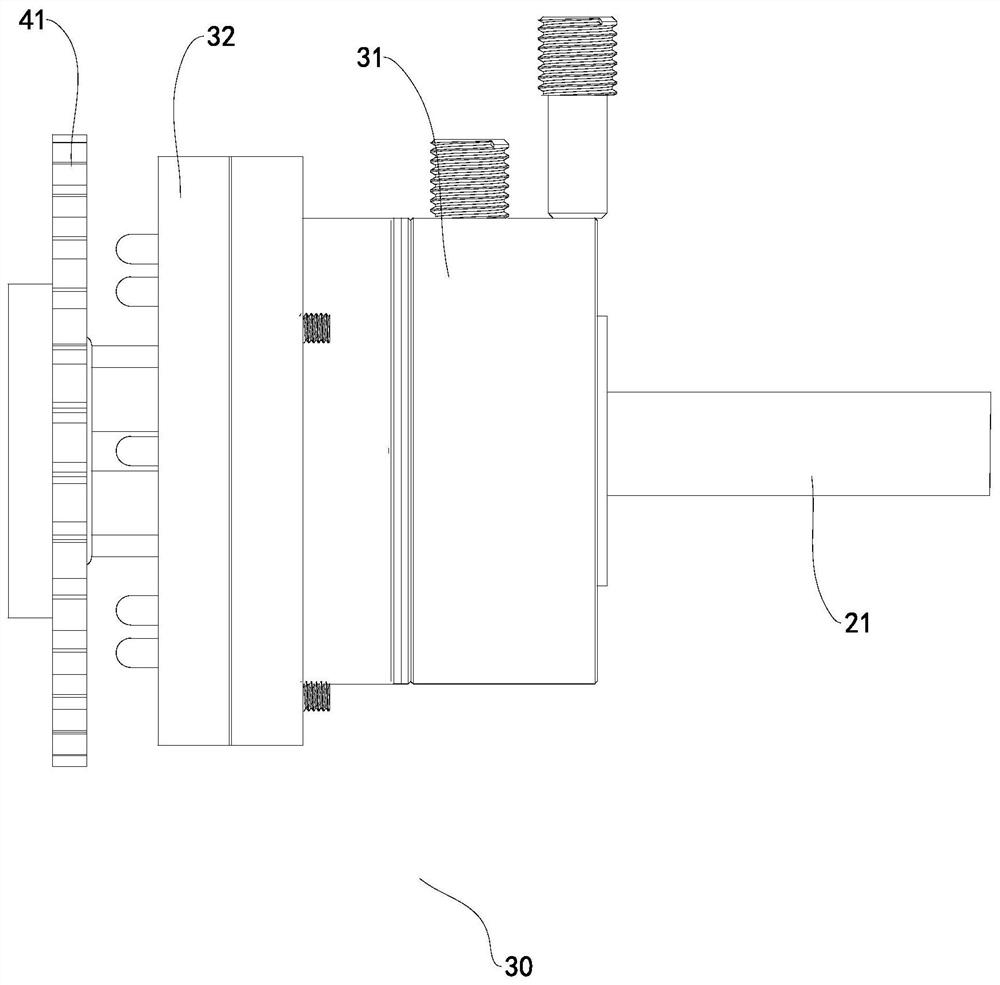

Image

  • Automatic tail drill equipment for horizontal lathe and horizontal lathe
  • Automatic tail drill equipment for horizontal lathe and horizontal lathe
  • Automatic tail drill equipment for horizontal lathe and horizontal lathe

Examples


Embodiment Construction

[0031] Preferred embodiments of the present invention will be described in detail below with reference to the accompanying drawings. Those skilled in the art will appreciate that these descriptions are only descriptive and exemplary, and should not be construed as limiting the protection scope of the present invention.

[0032] It should be noted that similar reference numerals denote similar items in the following figures, therefore, once an item is defined in one figure, it may not be further defined and explained in subsequent figures.

[0033] In the description of the present invention, it should be noted that the orientation or positional relationship indicated by the terms "upper", "lower", "front", "rear", "inner" and "outer" are based on the Orientation or positional relationship, or the orientation or positional relationship that the inventive product is usually placed in use, is only for the convenience of describing the present invention and simplifying the descrip...


PUM


Abstract

The invention discloses automatic tail drill equipment for a horizontal lathe. The automatic tail drill equipment comprises a tail drill device capable of moving on a rack, a power assembly, a clutch and a chain wheel assembly; the tail drill device comprises a movable base and a lead screw assembly arranged on the movable base, a tool is arranged at the front end of the lead screw assembly and driven by the lead screw assembly to stretch out and draw back front and back, and a manual crank is arranged at the rear end of the lead screw assembly; and the power assembly is connected with the lead screw assembly through the chain wheel assembly, the clutch is arranged between the power assembly and the chain wheel assembly, the clutch is used for connecting or disconnecting the transmission effect between the power assembly and the lead screw assembly, and the power assembly can drive the lead screw assembly to operate through the chain wheel assembly. Compared with a traditional manual swing tail drill device, the labor intensity of an operator is greatly relieved, so that the production efficiency is improved; and in addition, the clutch can connect or disconnect the transmission effect between the power assembly and the lead screw assembly so that a producer can switch between manual operation and electric operation, and therefore, the working mode of the tail drill equipment is optimized.

Description

technical field [0001] The invention relates to a horizontal lathe processing equipment, in particular to an automatic tail drilling equipment for a horizontal lathe. Background technique [0002] Horizontal lathe is a kind of mechanical processing equipment, which can turn and cut inner and outer circles, conical surfaces, end faces, boring, cutting grooves, drilling, knurling, etc. [0003] A horizontal lathe includes an equipment frame, a fixture for holding a workpiece, and a manual tail drill. The manual tail drill includes a base, a retractable tool on the base, and a manual handle; specifically, the tool can be a drill bit, a cutter, etc., and the manual tail drill The shaking handle can drive the tool to move forward or backward through the rotating shaft; the tool can perform various processing on the workpiece on the fixture. [0004] Since the tool is extended and contracted by the manual crank, the labor intensity is relatively high and the production efficiency...

Claims


Application Information

Patent Timeline
Patent Type & Authority Applications(China)
IPC IPC(8): B23B43/02B23Q5/40
CPCB23B43/02B23Q5/40
Inventor 石得银
Owner 宁波市鄞州塘溪银宏机械厂
Learn More