
Robot installation equipment with automatic braking function

A technology for installing equipment and automatic braking, applied in metal processing equipment, drilling/drilling equipment, metal processing machinery parts, etc., can solve the problems of drill bit breakage, waste of resources, and the connection between the drill bit and the component, so as to avoid breakage. , saving resources and improving efficiency

Inactive Publication Date: 2021-06-04
王旭
View PDF0 Cites 0 Cited by
  • Summary
  • Abstract
  • Description
  • Claims
  • Application Information

AI Technical Summary

Problems solved by technology

[0002] Robots have basic characteristics such as perception, decision-making, and execution. They can assist or even replace humans to complete dangerous, heavy, and complicated tasks, improve work efficiency and quality, serve human life, and expand or extend human activities and capabilities. Existing robots In the production process, it is assembled from multi-part components. In the process of component installation, it is necessary to drill holes in the robot components. During the use of the existing drilling rig, there will be a phenomenon that the drill bit and the component are stuck.
[0003] When the existing drilling rig drills the robot components, because the hardness of the components in different parts of the robot is different, when the drilling rig drills the robot components with higher hardness, the phenomenon that the drill bit and the robot components will be stuck, resulting in the drill bit Stress is generated between the shaft and the shaft, which in turn leads to the breakage of the drill bit, resulting in a waste of resources and a lot of time wasted, reducing the efficiency of robot component installation

Method used


Image

  • Robot installation equipment with automatic braking function
  • Robot installation equipment with automatic braking function
  • Robot installation equipment with automatic braking function

Examples


Embodiment Construction

[0024] The following will clearly and completely describe the technical solutions in the embodiments of the present invention with reference to the accompanying drawings in the embodiments of the present invention. Obviously, the described embodiments are only some, not all, embodiments of the present invention. Based on the embodiments of the present invention, all other embodiments obtained by persons of ordinary skill in the art without making creative efforts belong to the protection scope of the present invention.

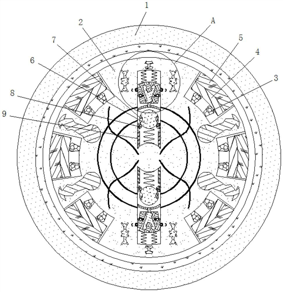
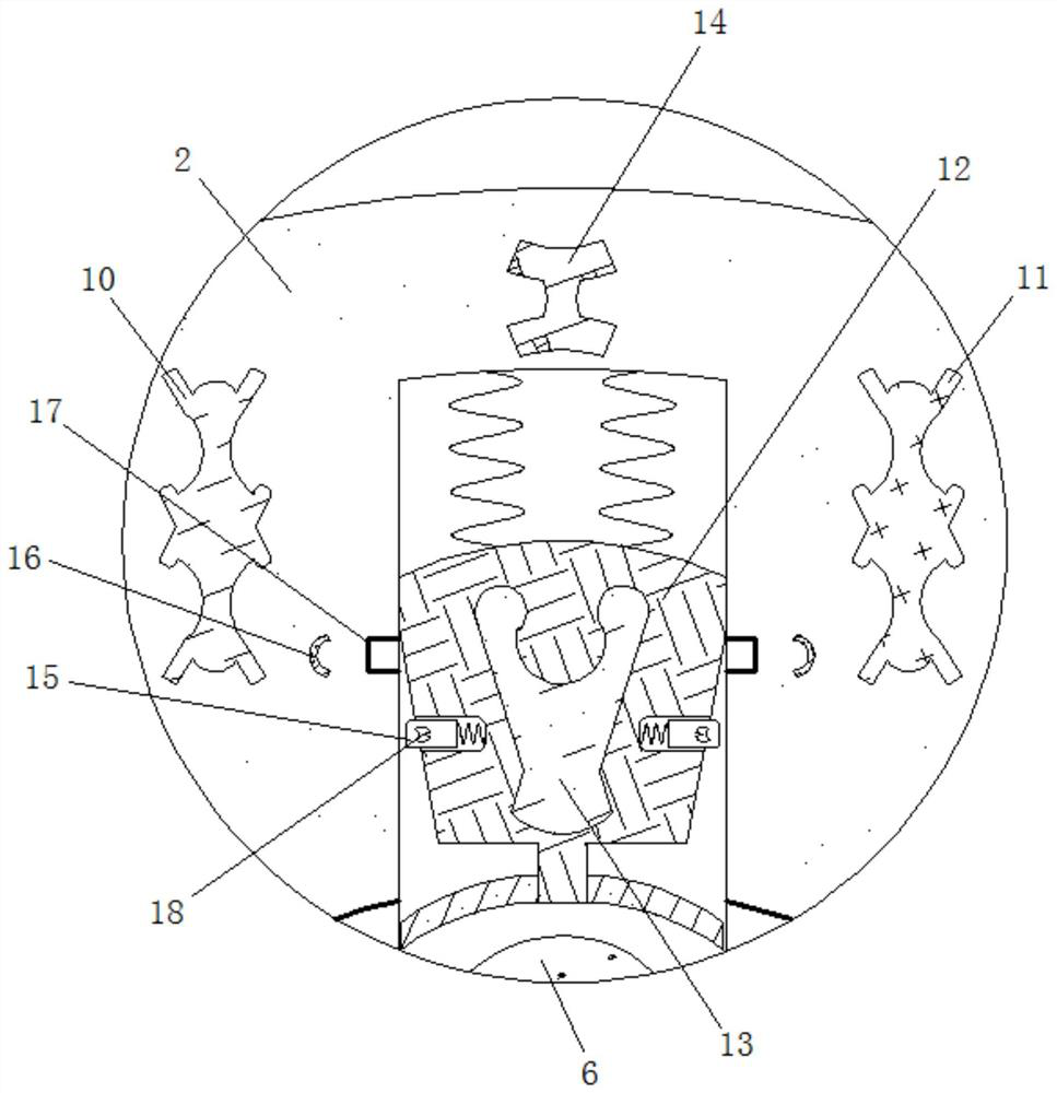
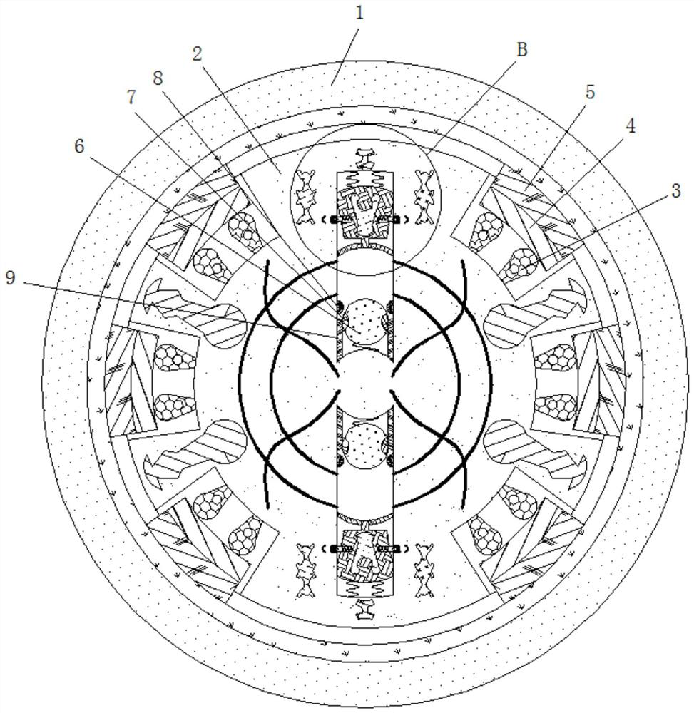
[0025] see Figure 1-4 , a robot installation device with automatic braking function, comprising a housing 1, the inner side of the housing 1 is movably connected with a rotating shaft 2, and the inner wall of the rotating shaft 2 is fixedly connected with a magneto-extensible block 3, the number of the magneto-extensible block 3 It is twice the number of friction blocks 5, and the magnetic elongation block 3 is electrically connected with the ball 6, and the ...


PUM


Abstract

The invention relates to the technical field of robot installation, and discloses robot installation equipment with an automatic braking function. The robot installation equipment comprises a shell, rotating shafts are movably connected to the inner side of the shell, magnetostrictive elongation blocks are fixedly connected to the inner wall of the rotating shaft, and electromagnetic plates are fixedly connected to the outer sides of the magnetostrictive elongation blocks. Friction blocks are fixedly connected to the outer sides of the electromagnetic plates, contact rails are fixedly connected to the inner walls of the rotating shafts, balls are elastically connected to the positions, close to the outer sides of the contact rails, of the inner walls of the rotating shafts, and contact points are fixedly connected to the inner walls of the balls. According to the robot installation device with the automatic braking function, by means of the characteristics of the electroactive polymer and the characteristics of the magnetostrictive elongation blocks, when a drilling machine drills a robot component with high hardness, the phenomenon that a drill bit and the robot component are stuck is avoided, stress is prevented from being generated between the drill bit and the rotating shafts, breakage of the drill bit is avoided, resources are saved; and meanwhile, a large amount of time is saved, and the robot component installation efficiency is improved.

Description

technical field [0001] The invention relates to the technical field of robot installation, in particular to a robot installation device with an automatic braking function. Background technique [0002] Robots have basic characteristics such as perception, decision-making, and execution. They can assist or even replace humans to complete dangerous, heavy, and complicated tasks, improve work efficiency and quality, serve human life, and expand or extend human activities and capabilities. Existing robots In the production process, it is assembled from multi-part components, and in the process of component installation, it is necessary to drill holes in the robot components. During the use of existing drilling rigs, there will be a phenomenon that the drill bit and the components are stuck. [0003] When the existing drilling rig drills the robot components, because the hardness of the components in different parts of the robot is different, when the drilling rig drills the robo...

Claims


Application Information

Patent Timeline
IPC IPC(8): B23B47/32B23Q11/04
CPCB23B47/32B23Q11/04
Inventor 王旭
Owner 王旭
Learn More