Concrete stirring equipment

A technology of mixing equipment and concrete, applied in the field of concrete mixing, can solve the problems of uneven mixing, affecting the next use of the equipment, and difficult to clean the concrete mixing equipment, and achieve the effect of improving flexibility and reducing noise.

Inactive Publication Date: 2021-06-04
王要磊
View PDF12 Cites 1 Cited by
  • Summary
  • Abstract
  • Description
  • Claims
  • Application Information

AI Technical Summary

Problems solved by technology

[0006] Aiming at the deficiencies of the prior art, the present invention provides a concrete mixing equipment, which solves the problem that the concrete mixing equipment is only stirred by a single stirring blade, and the stirring blade is not evenly stirred durin

Method used


Image

  • Concrete stirring equipment
  • Concrete stirring equipment
  • Concrete stirring equipment

Examples


Embodiment 1

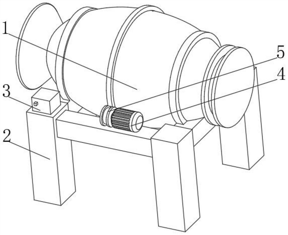
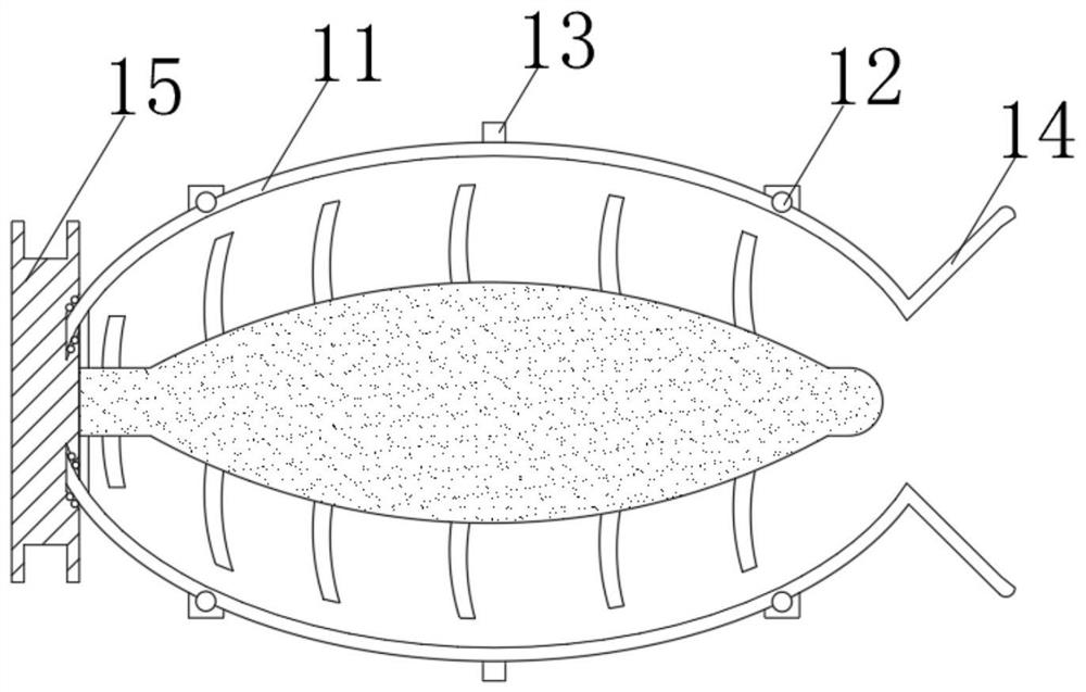
[0034] see Figure 1-3 , the present invention provides a technical solution: a concrete mixing equipment, including a mixing main body 1, a support frame 2 is arranged under the side of the mixing main body 1, and a controller 3 is fixedly connected to the side of the support frame 2 close to the mixing main body 1, and supports The side of the frame 2 close to the controller 3 is fixedly connected with a stirring main body driving motor 4, and the driving shaft of the stirring main body driving motor 4 is fixedly connected with a first driving wheel 5. The stirring main body 1 includes a stirring shell 11, and the side of the stirring shell 11 Both are fixedly connected with the first bearing 12, the second driving wheel 13, one end of the stirring shell 11 is connected with the feed hopper 14, and the end of the stirring shell 11 away from the feed hopper 14 is connected with the stirring mechanism 15 through the bearing rotation, and the stirring shell The body 11 is rotat...

Embodiment 2

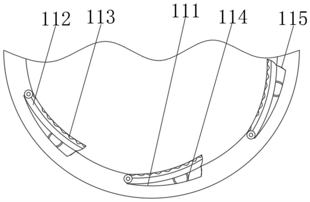
[0037] see Figure 2-5, the present invention provides a technical solution on the basis of Embodiment 1: a concrete mixing device, the mixing mechanism 15 includes a third driving wheel 151, and a chute 152 is opened on one side of the third driving wheel 151, and the inside of the chute 152 The second bearing 153 is fixedly connected, and the third driving wheel 151 is fixedly connected with a stirring device 154 near the side of the chute 152. The size of the second bearing 153 is suitable for the size of the connection block of the stirring housing 11, and the third driving wheel 151 is connected with a driving motor through a transmission belt, and the stirring device 154 includes a stirring housing 541. The inner axis of the stirring housing 541 is fixedly connected with a mounting plate 542, and the sides of the mounting plate 542 are fixedly connected with an electromagnet 543. 542 is fixedly connected with a buffer plate 544 and a guide rail 545 near the side of the e...

Embodiment 3

[0040] see Figure 5-6 , the present invention provides a technical solution on the basis of Embodiment 2: a concrete mixing equipment, the mixing blade 548 includes a blade housing 481, and a spring 482 is fixedly connected to the inner wall of the blade housing 481, and the spring 482 is far away from the blade housing One end of the body 481 is fixedly connected with a moving plate 483, and the side of the moving plate 483 away from the spring 482 is fixedly connected with a moving blade 484, and the end of the moving blade 484 away from the moving plate 483 penetrates the blade housing 481 and extends to the outside. The arc of the end away from the moving plate 483 is the same as the arc of the blade housing 481;

[0041] During use, the centrifugal force generated by the rotation will throw the moving blade 484 out of the blade housing 481, and the distance of the moving blade 484 will be limited by the moving plate 483 and the spring 482, so as to prevent the excessive ...


PUM


Abstract

The invention discloses concrete stirring equipment. The concrete stirring equipment is characterized in that a supporting frame is arranged below the side face of a stirring main body, a controller is fixedly connected to the side, close to the stirring main body, of the supporting frame, a stirring main body driving motor is fixedly connected to the side, close to the controller, of the supporting frame, and a first driving wheel is fixedly connected to a driving shaft of the stirring main body driving motor; and the main stirring body comprises a stirring shell, first bearings are fixedly connected to the side faces of the stirring shell, one end of the stirring shell communicates with a feeding hopper, the end, away from the feeding hopper, of the stirring shell is rotationally connected with a stirring mechanism through a bearing, the stirring shell is rotationally connected with the supporting frame through the first bearings, and one side of a second driving wheel is meshed with a first driving wheel. The invention relates to the technical field of concrete mixing. According to the concrete stirring equipment, concrete materials in the equipment can be stirred more uniformly, obstacles in the stirring shell are reduced, and convenience is brought to pouring out of the equipment and cleaning of the interior of the equipment by workers.

Description

technical field [0001] The invention relates to the technical field of concrete mixing, in particular to concrete mixing equipment. Background technique [0002] Concrete refers to the collective name of engineering composite materials that use cementitious materials to cement aggregates into a whole. The term concrete usually refers to the use of cement as cementitious material, sand and stone as aggregate, and water in a certain proportion. , The cement concrete obtained by mixing, also known as ordinary concrete, is widely used in civil engineering. After the concrete is mixed, it needs to be formed by mixing. [0003] For example, Chinese patent CN107053475B discloses a high-efficiency concrete mixing equipment, including a mixing drum, a number of mixing mechanisms, a driving mechanism and a central control mechanism. The mixing mechanism includes a mixing blade, a pin shaft, a stirring rod and a mixing assembly. The propeller and central control components include a c...

Claims


Application Information

Patent Timeline
IPC IPC(8): B28C5/24
CPCB28C5/24B28C5/2045
Inventor 王要磊
Owner 王要磊
Why Eureka
Try Eureka