Visual automatic cable twisting equipment and system thereof

A twisted cable and visual technology, applied in the field of visual automatic twisted cable equipment and its system, can solve the problems of waste of manpower and efficiency, trouble in production, inconsistent position in the direction of the cross section of the marking position, etc., so as to reduce the workload and reduce the quality of the optical cable. Guaranteed effect

Inactive Publication Date: 2021-06-04
SHANTOU HIGH TECH ZONE AOXING OPTICAL COMM EQUIP
View PDF3 Cites 1 Cited by
  • Summary
  • Abstract
  • Description
  • Claims
  • Application Information

AI Technical Summary

Problems solved by technology

[0002] At present, in the production process of optical cable extrusion, due to the rotation of the cable core, the optical cable will rotate after being extruded into the water tank, which will cause the cross-sectional direction of the special structure optical cable (non-circular optical cable) or the color stripe of the optical cable. The position changes during coding, resulting in inconsistent positions of the printing marks in the cross-sectional direction, which cannot meet customer requirements. At present, in order to cope with production, the manufacturer can only send a special employee to pass manual identification before the coding position Hand twisting is used to control the direction of the cross-section of the optical cable to control the position of the marking, which not only wastes manpower and efficiency, but also cannot fully guarantee the quality, which brings great trouble to production.

Method used


Image

  • Visual automatic cable twisting equipment and system thereof
  • Visual automatic cable twisting equipment and system thereof

Examples


Embodiment Construction

[0018] The accompanying drawings are for illustrative purposes only, and should not be construed as limitations on this patent; in order to better illustrate this embodiment, certain components in the accompanying drawings will be omitted, enlarged or reduced, and do not represent the size of the actual product; for those skilled in the art It is understandable that some well-known structures and descriptions thereof may be omitted in the drawings. The positional relationship described in the drawings is for illustrative purposes only, and should not be construed as a limitation on this patent.

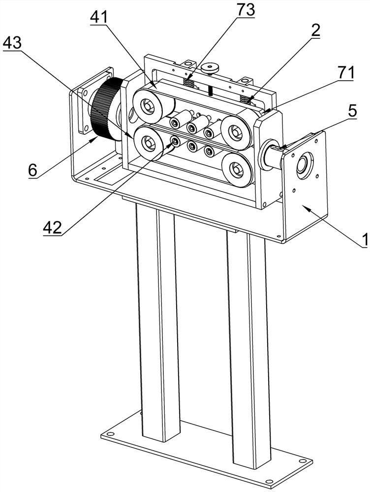
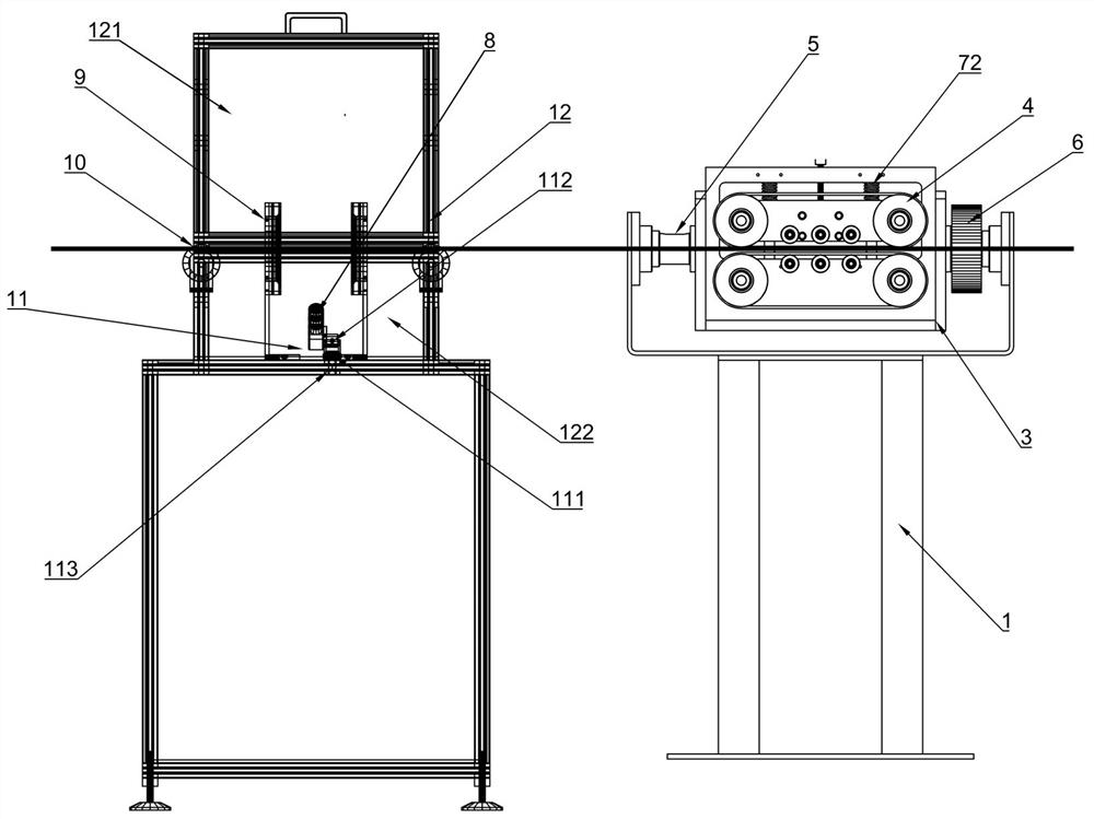
[0019] see Figures 1 to 2 As shown, it is a structural schematic diagram of the present invention. The visual automatic cable twisting equipment includes: a bracket, a driving device, a rotating base, a cable clamping assembly, a camera box, a camera and a ring light source. The driving device is installed on the bracket , the two ends of the rotating base are installed on the brack...


PUM


Abstract

The invention relates to the technical field of optical cable manufacturing equipment, in particular to visual automatic cable twisting equipment. A driving device is mounted on a support, two ends of a rotating base are mounted on the support through rotating shafts, the driving device drives the rotating base to rotate along the rotating shafts, a cable clamping assembly is mounted on the rotating base, a photographing box is arranged on the support, concave-surface rollers for supporting cables are arranged at square holes, a camera and an annular light source are arranged in the photographing box, the annular light source is located on the inner side of the square hole of the photographing box, the camera is electrically connected to an intelligent terminal, the intelligent terminal is electrically connected to a controller and the annular light source, and the intelligent terminal is electrically connected to the driving device through the controller. The equipment has the beneficial effects that the workload of operators is reduced, the quality of optical cables is ensured, the equipment judges the cross section directions of the optical cables (non-circular optical cables) of special structures or the positions of color bars of color-bar optical cables through the industrial camera and the visual system, the torsion angle pulse amount is calculated, and a synchronous motor is controlled to drive the cable twisting equipment, so that the torsion angles of the cross sections of the optical cables can be controlled according to the position of an ink-jet printer, and the positions of the marks on the optical cables are accurately controlled.

Description

technical field [0001] The present invention relates to the technical field of optical cable manufacturing equipment, and more specifically, to visual automatic cable twisting equipment and a system thereof. Background technique [0002] At present, in the production process of optical cable extrusion, due to the rotation of the cable core, the optical cable will rotate after being extruded into the water tank, which will cause the cross-sectional direction of the special structure optical cable (non-circular optical cable) or the color stripe of the optical cable. The position changes during coding, resulting in inconsistent positions of the printing marks in the cross-sectional direction, which cannot meet customer requirements. At present, in order to cope with production, the manufacturer can only send a special employee to pass manual identification before the coding position Hand twisting is used to control the direction of the cross-section of the optical cable to con...

Claims


Application Information

Patent Timeline
Patent Type & Authority Applications(China)
IPC IPC(8): B29C37/00B29C48/154B29C48/25G02B6/44
CPCB29C37/00B29C48/154B29C48/25G02B6/449B29C2037/80B29C2037/906
Inventor 林建新陈列庄经荣王镇杰王少桐
Owner SHANTOU HIGH TECH ZONE AOXING OPTICAL COMM EQUIP
Why Eureka
Try Eureka