Anti-blocking self-cleaning injection molding glue injection equipment

An injection molding and self-cleaning technology, applied in the field of injection molding, can solve the problems of slow blanking, mismatched supply, and reduced plastic stickiness, and achieve the effect of solving slow blanking

Active Publication Date: 2021-06-04
马鞍山康福塑料制品有限公司
View PDF22 Cites 1 Cited by
  • Summary
  • Abstract
  • Description
  • Claims
  • Application Information

AI Technical Summary

Problems solved by technology

[0004] In view of the deficiencies in the prior art, the object of the present invention is to provide an anti-clogging self-cleaning injection molding equipment to solve the problem that the current anti-clogging self-cleaning injection molding equipment in the prior art needs no cleaning during use. Discontinuously add new plastic blocks into t

Method used


Image

  • Anti-blocking self-cleaning injection molding glue injection equipment
  • Anti-blocking self-cleaning injection molding glue injection equipment
  • Anti-blocking self-cleaning injection molding glue injection equipment

Examples


Example Embodiment

[0025] Example 1

[0026] as attached figure 1 to attach Figure 5 Shown:

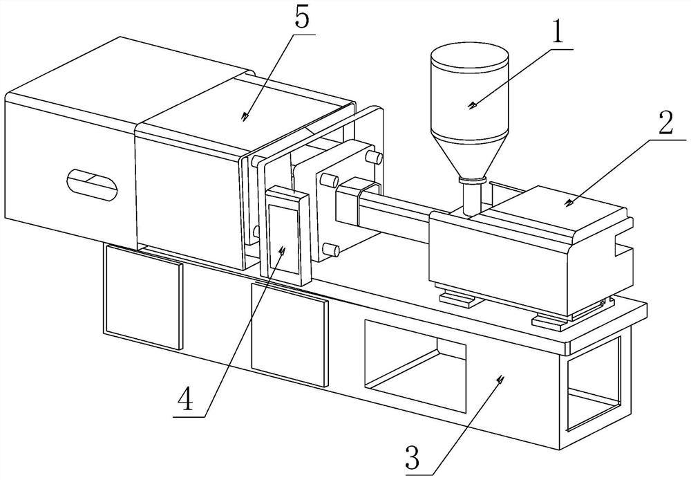
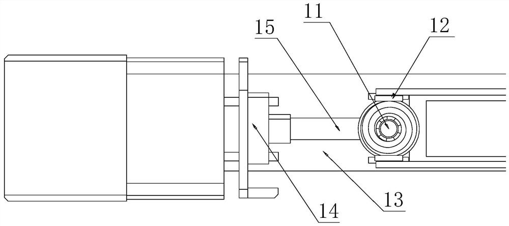
[0027] Its structure includes a chute 1, an equipment box 2, a carrier 3, a controller 4, and an injection molding chamber 5. The bottom of the hopper 1 is welded to the surface of the equipment box 2, and the equipment box 2 is bolted to the upper end of the carrier 3. fixed, the upper end of the carrier 3 is bolted to the injection molding bin 5, the right side of the injection molding bin 5 is hingedly connected to the controller 4, the controller 4 is matched with the internal clearance of the equipment box 2, and the lower chute 1 includes a lower Plastic port 11, clamping block 12, workbench 13, mold block 14, conveying pipe 15, both sides of the lower plastic port 11 are engaged with the clamping block 12, and the left side of the lower plastic port 11 is in clearance fit with the conveying pipe 15 , the conveying pipe 15 is in clearance fit with the surface of the workbench 13, the conveying...

Example Embodiment

[0033] Example 2:

[0034] as attached Image 6 to attach Figure 7 Shown:

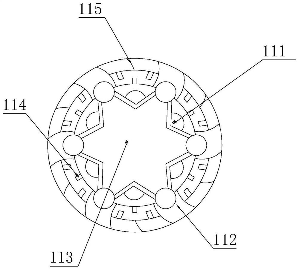
[0035] Wherein, the pendulum piece a11 includes an impact block b1, an elastic cord b2, a sliding chamber b3, a limit rod b4, and a strike chamber b5, the strike block b1 is movably matched with the strike chamber b5, and the strike chamber b5 Cooperate with the top of the sliding chamber b3 with a gap, the two sides of the sliding chamber b3 are embedded and connected with the limit rod b4, the limit rod b4 is movably matched with the surface of the elastic rope b2, and the elastic rope b2 is embedded with the inside of the impact block b1 connection, the impact block b1 is provided with six pieces, which are distributed on the inner side of the two walls of the limit rod b4 to limit its movable distance, and the rear end is embedded and connected with the elastic rope b2, wherein the impact block b1 is conducive to melting together at the bottom by impact The plastic is crushed to avoid the hole at...


PUM


Abstract

The invention discloses anti-blocking self-cleaning injection molding glue injection equipment. The anti-blocking self-cleaning injection molding glue injection equipment structurally comprises a discharging groove, an equipment box, a carrying frame, a controller and an injection molding bin, wherein the bottom of the discharging groove is welded to the surface of the equipment box; the equipment box is fixed to the upper end of the carrying frame through bolts; the upper end of the carrying frame is fixed to the injection molding bin through bolts; the right side of the injection molding bin is hinged to the controller; the controller is in clearance fit with the interior of the equipment box; the discharging groove comprises a plastic discharging opening, clamping blocks, a workbench, a mold block and a conveying pipe; the two sides of the plastic discharging opening are connected with the clamping blocks in a clamped mode; the left side of the plastic discharging opening is in clearance fit with the conveying pipe; and the conveying pipe is in clearance fit with the surface of the workbench. According to the anti-blocking self-cleaning injection molding glue injection equipment, a swing rod swings in cooperation with a spring rod under the compression of plastic raw materials, the swing amplitude of the swing rod is increased through the elasticity of an elastic strip matched with the top end of the swing rod, and the discharging speed of plastic in the swing rod is increased by increasing the swing amplitude, so that the phenomenon that the inner side of the plastic discharging opening is stuck by the plastic raw materials, and supply is insufficient is effectively avoided.

Description

technical field [0001] The invention relates to the field of injection molding, in particular to an anti-clogging self-cleaning injection molding equipment. Background technique [0002] Injection molding machine, also known as injection machine, is the main molding equipment for making various plastic products from heated plastic through molding molds. It can fill the mold cavity by applying pressure to the molten plastic to make it shoot out. ; [0003] However, there are the following deficiencies in the prior art: the current anti-clogging self-cleaning injection molding equipment needs to continuously add new plastic blocks into the interior of the injection molding machine during use, so that the molten plastic at the lower end of the feeding port At high temperature, the plastic block melts and sticks to the feeding port, which causes the inner wall of the feeding port to become smaller due to the melted plastic, resulting in slow feeding and mismatched supply. SUM...

Claims


Application Information

Patent Timeline
IPC IPC(8): B29C45/17B29C45/18
CPCB29C45/1753B29C45/18
Inventor 周林
Owner 马鞍山康福塑料制品有限公司
Why Eureka
Try Eureka